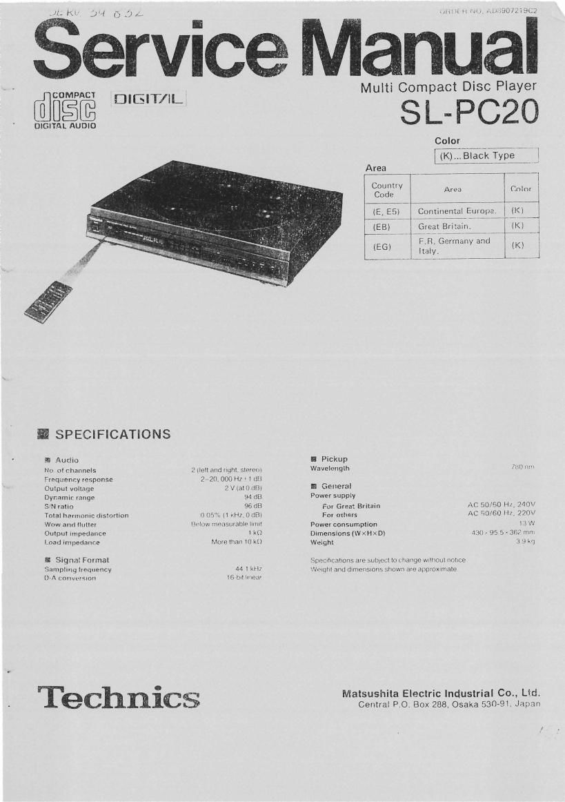
Technics SLPC 20 Service Manual

This is the 33 pages manual for Technics SLPC 20 Service Manual.
Read or download the pdf for free. If you want to contribute, please mail your pdfs to info@audioservicemanuals.com.

Page: 1 / 33
left right
Technics SLPC 20 Service Manual

Extracted text from Technics SLPC 20 Service Manual (Ocr-read)


Page 2

I CONTENTS

INSTALLATION .
ACCE§ORIES I 4 I .
PHECAUTION DF LASER DIODE . .

FRONT PANEL CONTROLS AND FUNCTIONS
CONNECTIONS .................... . .
NANDLINC PRECAUTIONS Eon OPTICAL PICKUP . .

INSTRUCTIONS FOR TRAVERSE OIL .

DISASSEMRLV INSTRUCTIONS . .
MEASUREMENTS AND ADJUSTMEN S
TERMINAL FUNCTION OF lc's
BLBCK DIAGRAM .........
INTERNAL CONNECTION 0F FL.

I INSTALLATION

Page
ScREMATIc DIAGRAM ....................... 26 ~ 33
TERMINAL GUIDE IF ICS,
TRANSISTORS AND DIODES . ..
WIRING CONNECTION DIAGRAM
PRINTED chculT aaARus.
REPLACEMENT PARTS LlsT . .
EXPLODED Vles ..
PACKING ........ .
RESISTORS at CAPACITaRs. . .
TRouaLESRooTINc FLOW criART.
TECHNICAL INFORMATION ......


I Transport lock I

The oplrcal pickup Is securad to prevent damage durlng transpon.
Be sure to release It pelore use.

1 2


a) Remove the
\clampen

.p

Lock shah Pull to unlnck
(in the locked
mndltloni

NOTE:

IF TRE UNIT Is TRANSPORTED

AGAIN, PERFORM THE

FOLLOWING STEPS:

l Turnthe pawercn and remove

all discs lrorn the trays,

2. PRESS THE DISC SKIP
BUTTON on the top panel and
turn the power oh.

. lnsen the clamper into the slot
on the bottom at the unit and turn
II clockwise.

4 Place lhs ml with the right

panel Iacrng downward
Press the lock shalt tn the LOCK
position (I -),

CAUTION:

no not Iranspon the unrt without

locklng the lock shah.

SEVERE DAMAGE WILL

u

sort cloth or swim meterrai
(to prevent scratches)

I Placement notes I

I PlIcc on a riot, level eunece so that the IronI-rear
lncllnltlnn does not exceed 5'.
I Avold place. Inch n the lallowlng:
.Near any equipment or cevrce that generates strong magnetism.
clan any heatageneratirlg ecuiprnent or device, or In any place
where the temperature is hrgh (40°C or hrgheri
IExIIemely cold pieces (ST or balcw)
-Near a lunar or TV (It may cause noise In the broadcast or
disturbance oi the TV picture)
oFur long periods at me In direct sunlrght
oln dusty or smoky locations
Iin locatrohs prone to vibrations,
oln locations where the rear panel is less than 10 cm (about 4')
away Irom the wall or back ol an audio rucko
owIthIn reach cl children.
I When carrying or atorlng the unit. hIndle It with care so It I:
not nublcchd to my strong humpl.
Always remove the arse belore slpnng the unIt lor any pelted or
time.
I To Ivoid problem: an to vlbrlllon.
one not place a book or sImIlar ohgect under this unit
IDa not roule the connection cables [at Ihls or other units) across
the operation penal, across the top, or under the unit.

RESULT.
- AC pow-r supply Cord ............... l ostueo cennectton cable . I putt cover ............. I
lsIAia7 .. .E, E5, E6] tSJP2249-3l (RYFoDloaKi
(SJAISZI .. .Eal
0 Remote central transmitter ........... I O BIncrin ............... 2
IEURGA'IESB) (UM-4NE/ZSI

m
IPRECAUTION 0F LASER DIODE

CAUTION: This product utilizes a laser diode with the unit turned "on'fi Invisible iaser radiation is emitted (rpm
the pick up lens.
Wave length: raonM
Maximum output radiation power from pick up: IDOuWIVDE

Laser radiation Item the pick up lens is satety level, but be sure the Iollowings:

1, Do not disassemble the optical pick up unit. since radiation trom exposed laser diode is
dangerous. .

2. Do not adlust the variable resistor on the pickup unit. It was already adjusted.

3. Do not look at the focus lens using optlcal lnstruments.

4. Recommend not to look at pick up lens tor a long time.

ACHTUNG: Dlesas produkt enthalt elne laserdlode. lm elngeschaltelen zuStand wird unsichtbare laserstrahlung
van der laserelhheit apgestrahlt.

Wallanlange: 7BOnM
Maxlmale strahlungslelstung der laserolnhelt: IOOHWIVDE

Dle strahlung an der lasereinhelt lst unqelahrlich. wenn iolgende punkta beachtet warden:

1. DIB laserelnhelt nlcht zerlegen, da dla strahlung an der lreigelegten laserdiode geiahrilch Ist.
2. Den werksseitlg lustlerten elnstellregler der laserelnrelt nlcht verstellen.

3, Nlcht mlt optlsciIen lnstrumenten In dle lokusslerllnse blicken,

4, Nicht fiber laugere zeit In dle lokusslerllnse bllcken.

ADVANSEL: I dottc l app-r t "Ivonne: laser.

Hui plhel
or In; unit

CLASS 1
LASER PRODUCl

Obs:
Annotate Innehéllar laser
Komponent av hoger IISerklaSs
an klass I

as

AflVAI'ISELlIsyrIIIgt llsulys
udstriles III ihlllng
uIIlmA DIREKTE
BESTRILINE,

DANEEII'InviSIDII VIIHSICIIT IIrlSIEIIthirI
512mm when Llserstreitlullg. worm

AMlckun IIMI,
AV - H"
PDE'UIIE'IEfiTEfiII IIIIIII on. SIIIIII Imam.

Page 5

, -lil i'
f
I. N . .
I DISASSEMBLY INSTRUCTIONS R 5 ° Removal oi the line out Jack P.C.B. WEN i Removal oi the clamp cover j
- I
I ' ' . f I .
Warning This product uses a laser diodes Re er to caution statements on page 2 . Prozcodfinn 1' Remove the 1 screw to)- Noam". 1- Release the 2 o|aw3_
ACHTUNG: 0 or: lasereinheitnicht zerlegen, 2 Ram ""3 1 mm" New _'25 2- Remove the clamp cover in the direction

oi the arrow.

0 Die lasereinheil dart nui gegen eine vorn hersteller spelitizierte einheit ausgeteuscht werden.

' This CD pllyIi is equipped with FPC hoerdl, to handle them with are during dinmmhiy end reuumbly. o
FTm Removel ol the dust cover "2 Removal oi the bottom cover
Procedure -Ramove the dust cover In the direction of F'OCMHN - Remove the 7 screws (0~0).
1 J the arrow. 2

D
ust cover Line out jack P.C.E.

CNBO1

7 ' Removal oi the clamp chassis

1. Remove the 3 screws (o~0).

ROMDVEI 0' "9 POWGI SOWCO P-C-B-r 4. Remove the power switch rod by using a
R N°- power trensiormer end power switch screwdrlver.
3 rod 5. Unsolder the terminals of the power
transformer.
Procedure 1. Remove the 3 screws (0~0). Note: Set the power switch to the "OFF"
23 2. Remove the 1 cannector(CN1). position. I

3, Remove the power source P.C.B. in the
direction oi the arrow.

0

Rel. No. i
a

i

Procedure 1. Release the 2 claws oi the tray holder.

Removal oi the disc tray

screwdriver


Power
Iranstoimel

Unsolder the Roi. No.
terminals 9

F n h 6 Removal oi the magnet
owersw c 10


Procedure -Release the 3 claws.

142~s
I _,7a9 2. Remove the disc tray in the direction of
'LN" Removal oi the operation P.c.B. the 0-
v .
Prov-dun l Removal oi the uporeuon P.C.B. 3 a
2a 1. Remove the 6 screws (o~o). M
2. Remove the 2 connectors (CM, 9"

Guam),

Page 28

4) The above operation will continue in order up to disc No. 5.

After play of disc No. the traverse deck will descend

and s top .

5 ends,

5) If a disc is not loaded on one of the trays, when that disc

F)

6)

tray reaches the optical deck position, the deck assembly will
still lift and search for the disc. After three search
trials. If the disc is not detected, the traverse lowers and
the carousel advances to the next disc position.

Programmed play

After steps A through D described above, play will be carried out
in accordance with the programmed order.

Carousel lock

If the power is switched off while play is in progress, becaues
the traverse deck will remain in the lifted up position, the
carousel will lock and it will not be possible to turn the
carousel by hand.

At the end of play or if play is stopped by the STOP button, the
traverse deck will descend. Under this condition, or if the
power is switched off this condition, it will be possible to turn
the carousel by hand. (The carousel lock will be released when
the traverse deck has lowered.)

2 . Loading mechanism

The loading mechanism performs the following two functions.

A)

B)

Rotation of the carousel in order
traverse deck (play position).

to carry the discs to the

Lifting up of the traverse deck when a disc reaches the play
position.

For these operations, the motor drive IC (IC-404) drives the loading
motor (M451) in accordance with the signal from the system control
IC-401, See figure 4.

The function of the loading motor

(M451) is to rotates the carousel

via intermediate gears or to lifts the traverse deck up or down via
a cam block.

-52_

«SD

2-1 Rotation of the carousel (Refer to figure 4)

A) In order for the carousel to rotate,

B)

C}

D)

. IC-404 supplies the motor
(M451) with the proper voltage supply polarity, (pin 10 negative
and pin 2 peeitive) in accordance with the signals from IC-401.

M451 turns in the counterclockwise direction, thus causing gears
A and B to turn.

Gear E drives gear C so that it turns in the direction indicated
hy arrow C, thus causing gear C to shift in the direction
indicated by arrow s and drive gear D, which in turn causes the
carousel to rotate.

Gear C is mounted to a lever
(refer to figure 3), and it
shifts either in the direction
indicated by arrow S or in the
opposite direction, in accordance
with the direction in which gear
B 15 turning.

Figure 3 Lever Position

LOADING MOTOR

MOTOR DRIVEIC
IC404

@8006
(-)(+)

(H)(L)(m


O408~O410

N I
3! 9 L'J (INVERTERS)

SYSTEM CONTROLIC
1C4m

CAROUSEL


Figure 4 carousel Drive System

- m _