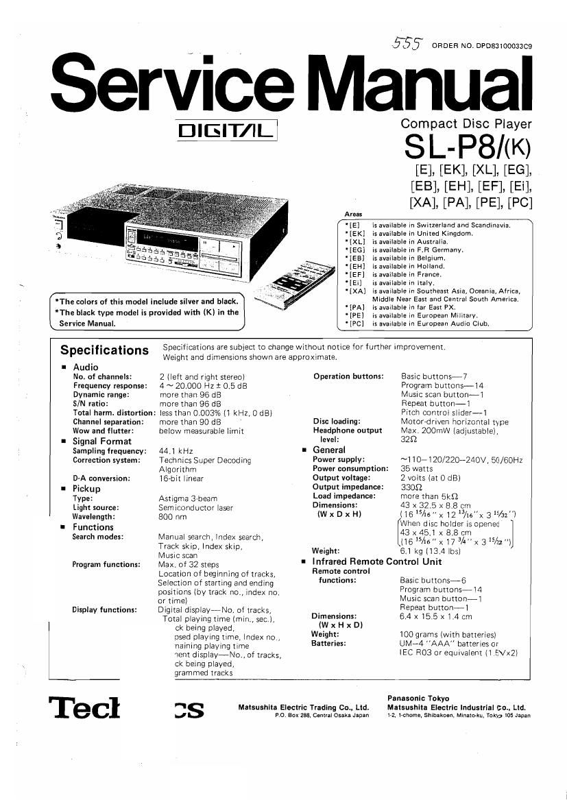
Technics SLP 8 Service Manual

This is the 119 pages manual for Technics SLP 8 Service Manual.
Read or download the pdf for free. If you want to contribute, please mail your pdfs to info@audioservicemanuals.com.

Page: 1 / 119
left right
Technics SLP 8 Service Manual

Extracted text from Technics SLP 8 Service Manual (Ocr-read)


Page 1

51;; ORDER NO.DP08310003309

SerViCe Manual

D-IElT/IL

The colors of this model include silver and black.
*The black type model is provided with (K) in the
\ Service Manual.

Compact Disc Player

S].- P8/(EK)

[E], [[EK]. [XL
[EB], [EH], [EF],[ [SI]:
[XA], [PA], [PE], [PC]

Areas

" [E] is available in Switzerland and Scandinavia,

' [EK] is available in United Kingdom.

" [XL] is available in Australia.

'[EG] is available in FR Germany.

' [EB] is available in Belgium.

'[EH] is available in Holland.

[EF] is available in France.

'[Ei] is available in ltaly.

[XA] is available in Southeast Asia, Oceania, Africa,
Middle Near East and Central South America.

lPAl is available in far East PX.

'[PE] is available in European Military.

[PC} is available in European Audio Club.

Specifications

Audio

No. of channels:
Frequency response:
Dynamic range:

S/N ratio:

Total harm. distortion:

Channel separation:
Wow and flutter:
Signal Format
Sampling frequency:
Correction system:

D-A conversion:
Pickup

Type:

Light source:
Wavelength:
Functions
Search modes:

Program functions:

Display functions:

Tecl

Specifications are subject to change without notice for further improvement.

Weight and dimensions shown are approximate.

2 (left and right stereo]

4 ~ 20,000 Hz 3 0.5 dB

more than 96 dB

more than 96 dB

less than 0.003% (1 kHz, 0 dB)
more than 90 dB '

below measurable limit

44.1 kHz

Technlcs Super Decoding
Algorithm

16-bit linear

Astigma 3rbeam
Semiconductor laser
800 nm

Manual search, index search,
Track skip, index skip,
Music scan
Max. of 32 steps
Location of beginning of tracks,
Selection of starting and ending
positions (by track no., index no.
or time)
Digital display-No. of tracks,
Total playing time (min, sec),
ck being played]
psed playing time, Index no,
naining playing time
went display-No, of tracks.
ck being played,
grammed tracks

SS

Operation buttons:

Disc loading:

Headphone output

level:
General
Power supply:
Power consump
Output voltage:

Output impedance:
Load impedance:

Dimensions:
(W x D x H)

Weight:

Infrared Remote Control Unit

Remote control
functions:

Dimensions:
(W x H x D]

Weight:

Batteries:

Malsushlte Electric Trading 00., Lid.
no. sex zae. Central Osaka Japan

Basic buttonsi7

Program buttons-l4

Music scan button-l
Repeat button-l

Pitch control slider-1
M0tor~driven horizontal type
Max. ZOOmW (adjustable),
329

~1107120/220-24OV, 50/60Hz
35 watts

2 volts (at 0 dB)

3309

more than Ekfl

43 x 32.5 x 8.8 cm
(165/15x12/tex 3 S/az'i
When disc holder is opened

43 x 45.l x 8.8 cm

(165/16" x 17 3A" x 315/32l
6.1 kg (13.4 lbs)

tion:

Basic buttons-6
Program buttons-i4
Music scan button-l
Repeat button-l
6.4 x 15.5 x 1.4 cm

100 grams (with batteries)
UNI-4 AAA batteries or
IEC R03 or equivalent (1 ,EVx2)

Panasonic Tokyo

Maisushlla Electric Industrial cm. Ltd.
172, 1~chome, Shibakoan, Minaioku, Tokyg 105 Japan

Page 2

I CONTENTS

Page Page
SAFETY PRECAUTION ......................... 2 EXPLODED VIEWS ................ . ...... 23 ~ 26
LOCATION OF CONTROLS . . . . . . . . . . REPLACEMENT PARTS LIST (Cabinet and Chassis Parts). . 29, 27
PLAYING A DISC ............ PRINTED CIRCUIT BOARD AND WIRING CONNECTION

HANDLING COMPACT DISCS. . . . . DIAGRAM .......................... 27 ~ 29
DISASSEMBLY INSTRUCTIONS . . . PRINTED CIRCUIT BOARDS ............ . .30 ~ 37
HOW TO REPLACE CHIPS ....... TERMINAL DESCRIPTION OF MICRO COMPUTER . . . . 38 ~ 40
HOW TO REPLACE lC's ......... HOW TO CHECK P,C.B ................... . .40 ~42
RESISTOR AND CAPACITORS ........... I . SCHEMATIC DIAGRAM . . . . . . . . . . .43 ~50
REPLACEMENT PARTS LIST (Electric Parts) ........... 21 BLOCK DIAGRAM. . . . . . 51 ~ 53

PACKING ........... 54

I SAFETY PRECAUTION

. Before servicing, unplug the power cord to prevent an electric shock.

. When replacing parts, use only manufacturer's recommended components for safety.

. Check the condition of the power cord. Replace if wear or damage is evident.

. After servicing, be sure to restore the lead dress, insulation barriers, insulation papers, shields, etc.

. Before returning the serviced equipment to the customer, be sure to make the following insulation resistance test to
prevent the customer from being exposed to a shock hazard.

(hetero--

I INSULATION RESISTANCE TEST
. Unplug the power cord and short the two prongs of the plug with a jumper wire

2, Turn on the power switch.

3. Measure the resistance value with ohmmeter between the jumpered AC plug and each exposed metal cabinet part, such as
screwheads antenna, control shafts, handle brackets, etc. Equipment with antenna terminals should read between 3M9
and- 5.2MSZ to all exposed parts. (Fig. A) Equipment without antenna terminals should read approximately infinity to
all exposed parts. (Fig. B)

Note: Some exposed parts may be isolated from the chassis by design. These will read infinity.

Antenna
terminal \

Exposed Exposed 5
metal metal
part part
Ohmmeter Ohmmeter
(Fig-Al (Fig. 8)
Reelstance=3M9-5.2MQ ResistancezApprox oo

4. If the measurement is outside the specified limits, there is a possibility of a shock hazard. The equipment should be
repaired and rechecked before it is returned to the customer.

Page 101

E. Focus gain adjustment

ll Connect the gain adjusting jig to the set.

(Red) ........... Jumper above l0651 on
08 P.C.B. (+15V) Refer to the drawing given at the
(Blue) ........... Jumper beside |C651 on ' end of the manual. (Page 15,)
08 P.C.B. (~15Vl
(Green) .......... Chassis
Connector ....... Pull out CN109 on 01 P.C.B. and connect it to the connector of thejig.

And connect the connector from jig to CN109.

2 Adjust the low frequency oscillator to 750Hz frequency and 150mVp-p output voltage, and
connect it to TEST pin OSC IN and GND of the jig.

3) Connect CH1 and CH2 of oscilloscope to TN and TP2 of the Jig. (TF3 is GND.)
Oscilloscope setting:

VOLT ........... 100 mV (both channels)
SWEEP .......... 2 ms
Input ........... AC

4) Set the power SW on" ofin and the rotary switch of jig to 1" and place the disc.

5) Turn power switch ON. When turntable begins to rotate, 750Hz signal appears on the OSCMO.
scope. Then adjust VR102 so that the waveforms of both channels are equal to each other.

TPl
Jig (a = b)

TP2

Page 107

11. PLL and CLV Adjustment

1) Shift the set to play mode. (An ordinary disc can be Used. Play it near the channel part.)

2) Connect CH1 and CH2 of the oscilloscope to test pins TP512 (FCLK) and TP513 (CLDCK) on

01 P.C.B.
Oscilloscope setting
Volt .......... 2V (both channels)
Sweep ......... 20 #5
Input select . . . . AC
Trigger ........ CH1+ CH2 (NORM) EB
Mode ......... ALT

3) Ground the both test pins MWB and TP514 (RESY) on O1 P.C.B.

4) The same operation as shown below is obtained when VR402 on 02 P.C.B. is moved. So, make
the fine adjustment of VR401 on 02 P.C.B. so that the conditions shown below are satisfied.

_ Control the values of @ and 9 outside the lock range (more

C -l :> than Bus both 6-) and 9)

GB 9

5) Adjust VR402 so that the conditions in the photo are satisfied.

-Lj- FCLK
-LCLDCK

12. Pitch Control Adjustment

1) Shift the slide VR of front panel to the center and turn ON the pitch switch.
2) Connect the frequency counter to TP512 (FCLK).
3) Adjust VR403 (02 P.C.B.) so that the frequency counter indicates 7.35 :0.03kHz.

Note: if frequency counter is not available, adjust VR403 so that the frequencies of TP5l2 nearly
agree when pitch switch is turned ON/OF F.

_12_