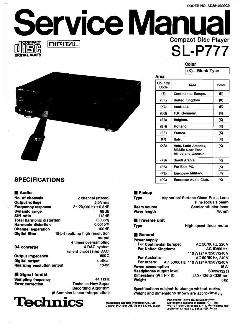
Technics SLP 777 Service Manual

This is the 45 pages manual for Technics SLP 777 Service Manual.
Read or download the pdf for free. If you want to contribute, please mail your pdfs to info@audioservicemanuals.com.

Page: 1 / 45
left right
Technics SLP 777 Service Manual

Extracted text from Technics SLP 777 Service Manual (Ocr-read)


Page 1

ORDER NO. AD8812N909

Service Manual

drmm' I:III3IT/I

DIGITAL AUDIO

SPECIFICATIONS
I Audio

No. of channels 2 channel (stereo)
Output voltage 2.5 Vrms
Frequency response 2~20,000 Hz:0.3dB
Dynamic range 98dB
SIN ratio 112dB
Total harmonic distortion 0.003%
Hermonlc distortion 0.0015%
Channel separation 100dB
Digital lllter 18-bit realizing high resolution
output
4 limes oversampling
DA converter 4 DAC system
(silent processing DAC)
Output Impedance 6000
Digital output optical
Realizing resolution output 18-bit

I Signal format
Sampling lrequency 44.1 kHz
Error correction Technics New Super
Decording Algorithm
(8 Samples LIneeHnlerpolatlon)

Technics

Mel-while Electric lnduelrlel Co. Ltd.
Central Po. Box 236. Oeeke 530-91, leIn World Trade Cooler Bldg. 4-1. Hemameleu-chu.

Compact Disc Player

SL- P777

Color
Area
6823; Area ' Color

(E) Continental Europe. (K)
(EK) United Kingdom. (K)
(XL) Australia. (K)
(EG) F.R. Germany. (K)
(EB) Belgium. (K)
(EH) Holland. (K)
(EF) France. (K)
(El) Italy. (K)
(XA) Asia, Latin America, (K)

Middle Near East,

Africa and Oceania.
(XB) Saudi Arabia. (K)
(PA) Far East PX. (K)
(PE) European Military. (K)
(PC) European Audio Club. (K)

I Pickup

Type Aspherlcal Surface Glass Press Lens
Fine focus 1 beam

Beam source Semiconductor laser

Wave length 780 um

I Traverse unlt

Type High speed linear motor

I General
Power supply

For Continental Europe: AGED/60 Hz, 220V

For United Kingdom: AC 50/60 Hz,
110VI127Vl220V1240V

For Australia AC 50/60 Hz, 240V
For others: AC 50/60 Hz, 110VI127V/220VI240V
Power consumption 15W
Headphones output level scrim/320
Dimensions (w x H x D) 430 x 126.5 x338mm
Weight 6 kg

Specifications subject to change without notice.
Weight and dimensions shown are approximately.

Pen-sonic Tokyo Selee asp-mum
usleushltl Electric Induliriei 60.. Ltd.

z-chome. Minan-ku. Tokyo 105. Japan

Page 2

I CONTENTS

PLACEMENT............ .....
ACCESSORIES .....
PRECAUTION OF LASER DIODE.
OONNECTlONs ..........................
REMOTE CONTROL TRANSMITTER
LOCATION OF CONTROLS
BASIC OPERATION .. .......
CONVENIENT FUNCTIONS
HANDLING PRECAUTIONS FOR OPTICAL PICKUP
INSTRUCTIONS FOR TRAVERSE OIL

(Part No. 522171.31) ..........
DISASSEMBLV INSTRUCTION
MEASUREMENTS AND ADJUSTMENTS
NEW SERVO GAIN ADJUSTER

(Servo Amp. Adjusting Fixture)
TERMINAL FUNCTION OF IO's..-

Page

I PLACEMENT

Before placement

The optical pickup is secured to prevent damage during transport.
Be sum to release it before use.

Lock shaft
(in the locked
condition)

(with inclination!) Pull to unlock.

Note:

When carrying this unit. be
sure to remove the compact
disc from inside the unit, and
press the lodx shaft to secure
the optical pickup. (Make
sure to place the unit with the
rear panel lacing downward.)

Soil doth or similar malarial (to prevent scratches)


INTERNAL CONNECTION 0F FL
BLOCK DIAGRAM .....
SCHEMATIC DIAGRAM
TERMINAL GUIDE 0F Ic's, TRANSISTORS AND
DIODES
WIRING CONNECTION DIAGRAM
PRINTED CIRCUIT BOARDS....
TROUBLESHOOTING GUIDE.
PACKING
RESISTORS l CAPACITORS
REPLACEMENT PARTS LIST
EXPLODED VIEW ..............
REPLACEMENT PARTS LIST ..
EXPLODED VIEW... .........
REPLACEMENT PARTS LIST ..
EXPLODED VIEW... ..............

Notes of placement

I Place on e not, level surface to that the tram-roar
Inclination don not exceed 5'.
I Avoid places such so the following:
oNear my equipment or device that generates strong magnetism.
IOn any heat~generating equipment or device. or in any place
where the temperature is high (40°C or higherl.
nExtremely cold places (5"C or below).
ONeaI a tuner or TV (it may cause noise in the broadcast. or
disturbance of the TV picture.)
I Do not place heavy oblects, other than system compo-
nents, on top of the unit.
I When carrying or storing the unit, handle" withcare so It Is
not «1le to any mung bumps.
Always remove the disc before storing the unit tor any period at
time.
I To avoid problems due to vibration.
00 not place a book or similar object under this unit.
000 not route the connection cables (at this or other units) across
the operation panel, across the top. or under the unit.

I ACCESSORIES
0AC power supply OStereo connection comical cable ........ 1 onemte control oBatteries ............ 2
cord ................ 1 cable ..... 1 transmitter .......... 1
SJ! 87 (E. E6. EB, (SJP22494) (SJPD16) (EUR64729) (UM-4NE/ZS)
EH. EF, El)
SJA1 73 (XL)
sun 93 (EK)

SJA168-1(XA, PA, PE, PC)
samaa (x3)