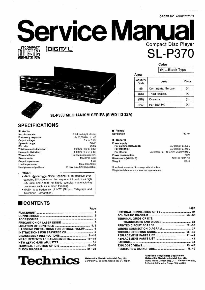
Technics SLP 370 Service Manual

This is the 39 pages manual for Technics SLP 370 Service Manual.
Read or download the pdf for free. If you want to contribute, please mail your pdfs to info@audioservicemanuals.com.

Page: 1 / 39
left right
Technics SLP 370 Service Manual

Extracted text from Technics SLP 370 Service Manual (Ocr-read)


Page 1

ORDER NO. A0900202509

Service Manual

Com act Disc Player
@CDMPACT DIEIT/I p

SI.- P370

Color
(K)... Black Type

DIGITAL AUDIO

SL-P333 MECHANISM SERIES (SlWD113-32A)

SPECIFICATIONS

I Audio

No. of channels 2 (left and right. stereo)
Frequency response 2-20.000 Hz, :1 (13
Output voltage 2 V (at 0 65)
Dynamic range 96 dB
SIN ratio 96 (35

Total harmonic distortion 0.005% (1 kHz. 0 dB)
Harmonicdistortion 0.003% (1 kHz,O dB)
Wow and flutter Beiow measurable limit
DA converter MASH' (4 DAG)
Output impedance 1 k0
Load impedance More than 10 m
Headphone output level 15 mw max. 320 (adlustable)

MASH

OMASH (Multistage Norse gaping) is an effective over-
sampling D/A conversion technique which realizes a high
S/N ratio and needs no highly complex manufacturing
processes such as a laser trimming.

OMASH is a trademark of NTT (Nippon Telegraph and
Telephone Corporation).

I CONTENTS


PLACEMENT
CONNECTIONS
ACCESSORIES ..........
PRECAUTION OF LASER DIODE .
LOCATION OF CONTROLS .......
HANDLING PRECAUTIONS FOR OPTICAL PICKU
INSTRUCTIONS FOR TRAVERSE OIL.
DISASSEMBLY INSTRUCTIONS .......
MEASUREMENTS AND ADJUSTMENTS
NEW SERVO GAIN ADJUSTER.
TERMINAL FUNCTION OF IC
BLOCK DIAGRAM ....................

. Mat-ushlta Electric industrial (:1, Ltd.
ec nlcs Central Po Box 2239, Osaka 530-91.Japan

Area
Country
Code Area Color
(E) Continental Europe. (K)
(GO) Third Region. (K)
(G N) Oceania. (K)
(PX) Far East-PX. (K)
I Pickup
Wavelength 760 nm
I General
Power supply
For Continental Europe: AC 50/60 Hz, 220 V
For Oceania: AC 50/60 H1240 V
For others: AC 50/60 H1110 V/II 27 V1220 W240 V
Power consumption 10 W
Dlmcnsions(WXHxD) 430x88x284 mm
Wolght 3.5 kg

Specifications subject to change without notice,
Weight and dimensions shown are approximate.

INTERNAL CONNECTION OF FL.
SCHEMATIC DIAGRAM
TERMINAL GUIDE OF ICS,
TRANSISTORS AND DIODES .
PRINTED CIRCUIT BOARDS ...... . 32~36
WIRING CONNECTION DIAGRAM ..... 37
TROUBLE SHOOTING GUIDE
REPLACEMENT PARTS LIST. 41 ~44
REPLACEMENT PARTS LIST .
PACKING ...............................
EXPLODED VIEWS ...........
RESISTORS & CAPACITOR

Panama: Tokyo Salo- Department
Mum-Mu Eloctrlc lndultrlll Cm, Ltd.

World Trace Canter Bldg.) 44, Hamamatsu-cno,
2~choma. Mlnato-ku. Tokyo 105. Japan

Page 2

L-P370

I PLACEM ENT
Before placement Notes of placement

The optical pickup is secured to prevent damage during transport. I This unit Is a precision instrument. Be sure to place It on a

Be sure to release it beiore use, "at surface.

I Avoid places such as the following:

ONear any equipment or device that generates strong magnetism

OOn any heal-generating equipment or device, or in any place
where the temperature is high (350 or higher).

OEXIremely cold places (5°C or below).

INear a tuner or TV (It may cause noise in the broadcast, or
disturbance of the TV picture.)

I When carrylng or atorlng the unit, handle it with care so it is

not subjected to any strong bumps.

Lock shaft Pull to unlock.
(in the locked

condition)

(with inclination!)

Note: Always remove the disc before storing the unit for any period 01
When carrying this unit, be time.
suretoremovethe compact I To avoid problems due to vlbratlon.
disc from inside the unit. and 000 not place a book or similar object under this unit
press the lock Shall 0 secure 000 not route the connection cables (of this or other units) across
the optical DiCkUD- (Make the operation panel, across the top. or under the unit.

Soft cloth or similar material sure to place the unit with the

(to prevent scratches) rear panel facing downward.)

I CONNECTIONS

Turn power off on all components betore making connections.

OOptlcal output terminal (DIGITAL OUT/OPTICAL)
This terminal can be used for connection with other equipment that
has a digital input terminal, such as an amplifier. by using an optical
cable (optional). A dustvprotection cap is inserted in this terminal
Remove this cap only when a connection is to be made to this
terminal. (For Continental Europe)

J

CLASS 1
LASER PRODUCT

LUOKAN 1 LASERLAITE


Note:
The configuration oi the AC outlet and
/* AC power supply cord differs according
to area,
_ _ , Rear panel
/ of this unit
[-mln M m u.
a e m i ' a a
l_
L__J l L'_._i
(R) (L) y
.- AC power supply cord
Stereo connection cable (included)
(included) L-type cable .:
(L) (not included)
To the CD" or "AUX" Household
terminals of the To the SYNCHRO EDIT" terminal at the AC WW
amplifier (R) Teohnics tape deck
Note:
Be sure to connect the stereo connection cable with the amplifier
when using the synchro edit function even if the optical cable
has been connected.
0 AC power supply cord .............. 1 - Stereo connection cable ........... 1 ° Remote control transmitter ......... 1
SJAlB'I (E) (SJP2249-3) (RAK-SLSOOSE)
[ SJA173 (GN) ] - Batteries .......................... 2
RJAOOOA (Go, PX) (UM-ANEIZS)