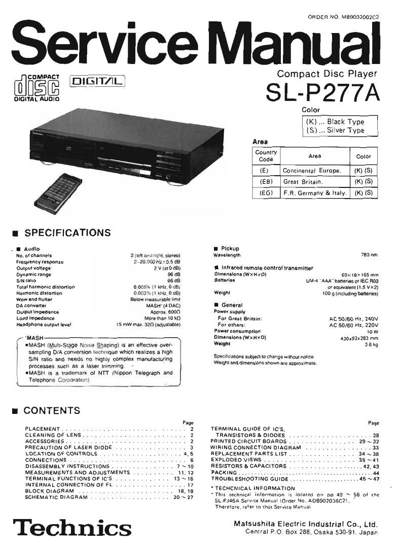
Technics SLP 277 A Service Manual

This is the 29 pages manual for Technics SLP 277 A Service Manual.
Read or download the pdf for free. If you want to contribute, please mail your pdfs to info@audioservicemanuals.com.

Page: 1 / 29
left right
Technics SLP 277 A Service Manual

Extracted text from Technics SLP 277 A Service Manual (Ocr-read)


Page 1

ORDER NO. MBQOOQOOZC2

Service Manual

COMPACT WI-1 Compact Disc Player

WEI-9% SL-P277A

Color

(K) Black Type
(S) Silver Type


Area

Country
Code Area 0010!

(E) Continental Europe. (K) (S)
(EB) Greal BriIain. (K) IS)
(EG) FR. Germany 8 IIaIy. (K) (S)

I SPECIFICATIONS

_ I Audlo I PIckup
No, 0! channeIs 2 um and thI. slereoI Wavelength 730 Am
Frequency (espanse 2- 20 000 Hz ' 0.5 53
Output voIlager 2 V IaIDdB) I Infrared remote controftransminu
Dynamln range 96 dB Dlmenslona MXHXD) 50>: lax 165 mm
SIN ram: 96 dB Banule: uM-d "AAA banenes or IEC no.3
Talal hamonlc dlslonlon o 005% H RM. 0 dB: 0' equwalem (15 Vsz
Hammnlc ulslanlon 0 003% II nHz. 0 as) WeIgm 100 9 (Including banenes;
wow and 11mm Belaw measuxanle limll A
DA convaner MASH' (4 DAG) I General
Ouxpul Impednnoe Approx Goon Power supply
Load Impedance Moreman I0 kn For Great Brimin: AC 50/60 Hz, 240V
Headphone aulpul level ISmW max. 326 (adgusIableI For when: AC 50/60 Hz, 220V
Power consumptlon 10 w
'MASH Dimensions (WXHxD) 430192x283 mm
UMASH (Mulu-Slgge Nwse gaping] >5 an eflecnve over- WEI" 35 '49
samplmg D/A conversion vechnuque which remlzes a high _ , _
SIN ralio and needs no higth compIex manulaclunng Spemhcahons subgecI Iocnange WIIhoulnolIce

> We: hlanddimensionsshownm ' .
processes such as a Iase! Inmrnmg , g eappwmala

IMASH I: a trademark oI N'IT (Nrwon TeIegraph and
Tevephone Corporahonl

I CONTENTS

Page Page
PLACEMENT ............................. 2 TERMINAL GUIDE OF IC'S,
CLEANING 0F LENS. . . I , 2 TRANSISTORS 81 DIODES .................... 23
ACCESSORIES ....... I I . . 2 PRINTED CIRCUIT BOARDS .........
PRECAUTION OF LASER DIODE , . . 3 WIRING CONNECTION DIAGRAM .....
LOCATION OF CONTROLS ...... . I I 4,5 REPLACEMENT PARTS LIST ......... . . ,.
CONNECTIONS ............................ 6 EXPLODED VIEWS ...................... 39 ~41
DISASSEMBLY INSTRUCTIONS .......... I . . 7 ~ 10 RESISTOHS BI CAPACITORS ................

MEASUREMENTS AND ADJUSTMENTS . . .

TERMINAL FUNCTIONS OF ICS TROUBLESHOOTING GUIDE ..............

I A .

{givm'kgg'lficncm OF FL ' TECHCNICAL INFORMATION
' Thks lechnicaI informaxion is located on po 49 ~ 56 of (he

HE ATI DIA H ................. I ~ I
so M C 5 AM 2° 27 SL-PJASA Sen/Ice Manual {Order Nu,A0390203602)_
Therefore, refer :0 (ha Service Manual

. Matsushita Electric lndusIrial Co., Ltd.
60 I I lCS Central P.0I Box 258. Osaka 530-91. Japan

PACKING ...................

Page 2

L-P277A

I PLACEMENT

I Before placement

Two transport secmrty devices are secured to prevent the optical
pickup from damage dunng transport.
Be sure to release them belore use.

LOCKED RELEASED
i;
-
v
O x Insert them here alter remowngr
Turn clockWise by $0 to secure
them.
\. . .
Solt cloth or similar material (to
revent scratches
O P )
Note:

When transponing the unit. be sure to remove the compact disc
lrom inside the unit. And replace the transport security devices
again lollowing the reverse order not to damage the oplical pickup.

I CLEANING OF LENS

H the lens is stained causing sound skip or operation lailure,
open the top cover by pressing the open button, and clean
the lens.

I To remove dust or dirt
Blow the lens with the blower prowded in the cleaning kit
to remove du5t or dtrlt

Oust or din

Fingerprint

0 To remove fingerprint

it the blower is not enough moisten the cotton rod
with the lens cleaner solution and wipe the lens wrth it
from center ol the lens to outside.

I ACCESSORIES

0 AC power supply cord .......... 1
[SJA187 (E. eel]
SJA193 (EB)
0 Remote control transmitter ....... 1

[Eunemee (Ki ]
euns4797 (S)

I Notes of placement

I This unlt Is a precision instrument. Be sure to place ll on a

net surlace.
I Avoid places such as the lollowlng:

INear any equipment or device that generates strong magnetism.
OOn any heatsgenerattng equipment or devtcer or in any place

where the temperature is high (35°C or higher).
0Extrernety cold places (5°C or below.

INear a tuner or TV (It may cause netse in the broadcast. or

disturbance ol the TV picture.)

I When carrying or storing the unit, handle It with care so It Is

not subjected to any strong bumps.

Always remove the disc Delore storing the unit lor any period ol

time.
I To avoid problems due to vlbratlon.
-Do not place a book or similar object under this unit.

IDo not route the connection cables lot this or other units] across

the operation panel. across the top, or under the unit.

Cautions:

0 Do not directly apply the cleaner solution to the lens.
Do nor apply too much solution to the cotton rod or
otherwise the solution wrll flow into the player.

- Wipe the lens caretully. Do not glue too much stress to
the lens or otherwise it may scratch the lens or cause
optical pickup trouble.

0 it the solution should be too much applied, wipe the
lens with a dry cotton rod.

Lens cleaning kit (Part No. . SZZPIOSBC)


Canon
rod
Cleaner
Blower
0 Stereo connection cable .......... l
(SJP2249-3)
0 Batteries ........... . .......... 2
(UM-4N E/ZS)

Page 8

S -P277A

Rats N0 Removal of the main P.C.B.
How to check the main P.C.B.
Procedure _. -_
12*3.4*5 When checking the soldered surface of the main P,C,B,

and tepiacing the parts, do as Shown beiow.

I. Dont remove the connectorg (CNIZ, CN4011
CN431) and flat cable (CNN).

2 Connect the main P.C,B. ground terminal (LINE
OUT terminal) to the Chassis with a lead wire.

3. Connect the operation ROB. ground terminal to
the chassis with a lead wire.

Retention,
Posls

0
1 Remove the 4 screws) ~ (N
2. Remove the 3 connectors (CN72, CN401, CN431)
3. Remove the 1 flat cabie (CNN).
4 Lift the mam PCB. off the retention posts on the
chassis.
5. Remove the main PCB. in the direction of the
arrow.
RetsNo. Removal of the disc lid and holder (
Procedure 1. Remove the Spring 3. FUN out the holder in the direction of the arrow
1-5 2. Move the disc lid in the direction of the (@i.

arrow (0)and ouil outthis in the direction
of the arrow (@i.

Ho'idar

Caution: Be sure to handle the ginah ball carefulty.

:1 Remove the ring In the tiiiettion of the arrow

t9),

Page 17

I INTERNAL CONNECTION OF FL

0 Grid assignment

E3E?E

m11= .= =

r-«fi

o Anode connection

150 146 13C; 120 11G 10G 96 26
1 a 15 12 9 6 3 arms a a
b :51 2 E .151. i _. 1a b
c W E W (-6) 1 (3) c 9
d 16 i3 i0 7 . A 1 d d
, e 1 (1121 . (3) (7) i' in ii) a . e
E W . (1-3) W W : 171' W T F
- ' M 11 a 5 2 g
. fl - 111i la) (Si in .
i - 1 11-41 1 W W W W .
0 Pin connection
361353433323130292827262524232221201918 5 4 3 2 1
FFNN bcd f h115141312N B 654321NNFF
2 2 P p a e E G G G G P G G P P
Note UNP-
2_)i<'1.i«*2
ELMO-[50 ------ Grid

l BLOCK DIAGRAM

OPHCAL PICKUP UNIT

Szfivo Cl.rU '

an.

MAIN CrRCUlY

mum
a

I POWER SUFPLV CIRCUIT

1 L._f_-. 9

m:

MNE'lGHflJWZ
svsirw minor 3

1-. . .
1 7 ~ .I D PM"
mm. .
.. _ . " 55... NJ
. 5......» I \ D - ,1 Dr
WA rm m ,
-- w
. w a, 11.; law».
1 \ "5 ..= 7-1 1 7
1 l T ' l\ -
l 1 7
E l A
- 7W: . mm... -
J m 7
1 m [W515 I} gt-wiouu
I J _ _
1 I 1 g 7 is a ,
.lfi, 1' w... --- - 1 q,
I... :ggwr 41 mum H
mm. 7. r .
momm
.c .
1: ,
- , .1 .M. r . I
l 1 I '
.J
i»... .
. ,

l are. 5 SNIL

1:515?

I
1 nznsmwa
(1 ~.:rv P < l
- .. fl 1 l - 1 .
1~ 1mm -. my \ V 7 - \ I
_7 3v _ .4 ._
-!11. . n mam
I - Acrv ' I I .
OPERAHON cmcmr Lemme UNIT
Note]
- --- Audio signal.
RAD ( : Current oul ut of iriie rated [R22 A Rel] . -
nu inout currerijts. g ESSEX Radial mm d'g'mL P40~44 Key return Signal. LRCK LIR data discrimination clock 188,2KHzl
30 BS Con r 3' far ' cl at c rc T}! R DGTO~15 Key scan signal and FL dlgit signal. (LRCLKJ
~ . : 1 .
m . . D to i: I a i uir| 'E-Ijg adiai error Signal for LAG network. SEGD~8 FL segment signal. SFIDATA Serial data output (MSB first)
mp 0'" em or was Elfin mm" mm k" '3 WI" and f°°" "m MCLK Data clock tor MDATA. SCLK Serial bil clack (2.82MHzl.
D1 ~ D4 ; Pholodlode currents. TL Track loss signal. SL171 Sub-code Q dais iSRCKJ
FE . Focus error signal. Div4 Radial error dlflltal dewded by four. m Data frame clock (7.35KHzl. MEMP Deemphasis command (Active High)
FE lag ; Focus error signal lor LAG network. HF/FIF Data. BLKCK Sub-code C! dam block clock ,5 Hz] (EMPHl
HF : HF output ior DEMOD. DD Drop-out detection signal [Active High). W Reset command [Active Low) P271P6l Svnchro rec control
HFD : HF detector output for DEMOD. SRF Sliced RF signal. lFiSTBl ' lFin Remote control signal
[PU-H) EFM Modu'ai'o" dala- TRON Tracking servo 0N command (Active Law). 334151)) 384': IIBBGMMHI) signal
HFln : HF current input, PCK PLL extract clock [4.2336MHzl. EC Turntable motor drive 519" DEMPH DMmphasis 0N signal
LM : Laser monitor diode Inpul. FPC PLL lrequency comparison signal. PC Turnlabla motor ON command [Active Low]. TX Digital signal output
Lo 1 Laser amplifier current outpm. STAT Status command ior CFiC etc. SMCK . System clock 2335,... DO~7 15K HAM data
Fiat : Radial error signal 1 [summation oi amplified DMUTE Data mute command. (OSC1IOSC2l FlAMO~10 16K HAM address signal
men 03 at! '34)- MDATA Mode control data. OE - Read out enable. P25 (MUTE) Muiing conirol SIQHHI
R92 3 Radial 9" 59" 2 mmam" 0' amplified MLD Load command lor mode control data WE Write enabIE. P26 3 Loading motor control signal
currents D1 and DE). lActlve LDW). [OPENICLOSEI

_1g,

_19_