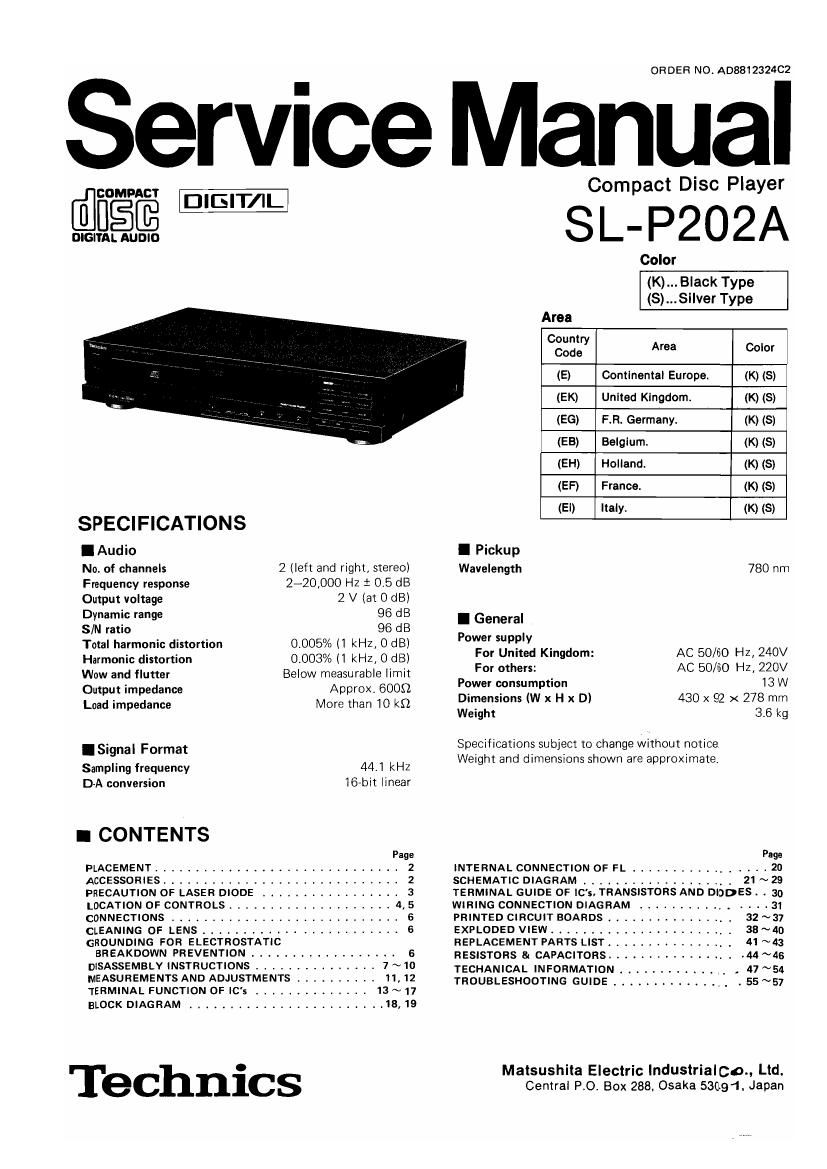
Technics SLP 202 A Service Manual

This is the 46 pages manual for Technics SLP 202 A Service Manual.
Read or download the pdf for free. If you want to contribute, please mail your pdfs to info@audioservicemanuals.com.

Page: 1 / 46
left right
Technics SLP 202 A Service Manual

Extracted text from Technics SLP 202 A Service Manual (Ocr-read)


Page 1

ORDER NO. A08812324C2

Service Manual

@figfi @@

DIGITAL AUDIO

Compact Disc Player

SL- P202A

Color

SPECIFICATIONS
IAudio

No. of channels
Frequency response

2 (left and right, stereo)
2-20,000 Hz 1 0.5 dB

Output voltage 2 V (at 0 dB)
Dynamic range 96 dB
SIN ratio 96 dB

Total harmonic distortion
Harmonic distortion

Wow and flutter

Output impedance

Load impedance

0.005%(1 kHz, 0 dB)
0.003%(1 kHz, 0 dB)
Below measurable limit
Approx. 6009

More than 10 k9

ISignal Format

Sampling frequency 44.1 kHz
D-A conversion 3-bit linear
I CONTENTS
Page
PLACEMENT .............................. 2
ACCESSORIES ............................. 2
PRECAUTION OF LASER DIODE ................. 3
LOCATION OF CONTROLS .................... 4, 5
CONNECTIONS ............................ 6
CLEANING OF LENS ........................ 6
GROUNDING FOR ELECTROSTATIC
BREAKDOWN PREVENTION .................. 6
DISASSEMBLY INSTRUCTIONS ............... 7 ~10
MEASUREMENTS AND ADJUSTMENTS . . . . 11,12
TERMINAL FUNCTION OF IC's ......... . 13 ~ 17
BLOCK DIAGRAM ........................ 18, 19

Technics

(K) Black Type
(S)...Si|ver Typo
Area
6823? Area Color
(E) Contlnontal Europa. (K) (S)
(EK) United Kingdom. (K) (S)
(EG) F.R. Germany. (K) (5)
(EB) Belgium. (K) (3)
(EH) Holland. (K) (8)
(EF) France. (K) (S)
(Ei) Italy. (K) (S)
I Pickup
Wavelength 780 m
I General

Power supply

For United Kingdom:

For others:
Power consumption
Dimensions (W x H x D)
Weight

AC 50/60 Hz, 240V
AC 50/60 Hz, 220V
13 W

430 x 92 x 278 mm
3.6 kg

Specifications subject to change without notice
Weight and dimensions shown are approximate.

INTERNAL CONNECTION 0F FL
SCHEMATIC DIAGRAM .....

.............. 21 ~29

TERMINAL GUIDE OF Ic's, TRANSISTORS AND DIODES . . 30

WIRING CONNECTION DIAGRAM ................ 31
PRINTED CIRCUIT BOARDS ................ 32 ~37
EXPLODED VIEW ....................... 38 ~40
REPLACEMENT PARTS LIST ................ 41~43
RESISTORS 81 CAPACITORS ................ .44 ~45
TECHANICAL INFORMATION ............. . 47 ~54
TROUBLESHOOTING GUIDE ............... . 55~57

Matsushita Electric lndustrialco., Ltd.
Central PO Box 288. Osaka 53091. Japan

Page 2

SLAP202A

I PLACEMENT

Before placement

Two transport security devices are secured to prevent the optical
pickup from damage during transport,
Be sure to release them before use.

LOCKED RELEASED

("iii


Pull
® out

(with .
Insert them here after removrng.

Turn clockwise by 90° to secure
them.

Soft cloth or similar material (to
prevent scratches)

Note:

When transporting the unit, be sure to remove the compact disc
from inside the unit. And replace the transport security devices
again following the reverse order not to damage the optical pickup.
(Make sure to place the unit With the rear panel facing downward.)

I ACCESSORIES

Notes of placement

l Place on a flat, level surface so that the tront-rear
inclination does not exceed 5".
I Avoid places such as the lollowlng:
ONear any equipment or device that generates strong magnetism.
~0n any heat-generating equipment or device, or m any place
where the temperature ls high (40°C or higher).
0Extremely cold places (5°C or below).
0Near a tuner or TV (it may cause noise in the broadcast, or
disturbance of the TV picture.)
I Do not place heavy objects, other than system compo-
nents, on top at the unit.
I When carrying or storlng the unit, handle it with care so It is
not subjected to any strong bumps.
Always remove the disc before storing the unit for any period of-
time.
I To avoid problems due to vibration.
000 not place a book rr similar object under this unit.
000 not route the connection cables (of this or other units) across
the operation panel, across the top, or under the unit.

oAC power supplycord ,, 1

SJA187 (E, EG, EB, EH, EF, Ei)
SJA193 (EKi

OStereo connection cable . . . . 1
(SJP2249-3)

Note: Configuration 01 AC power supply cord differs according to area.