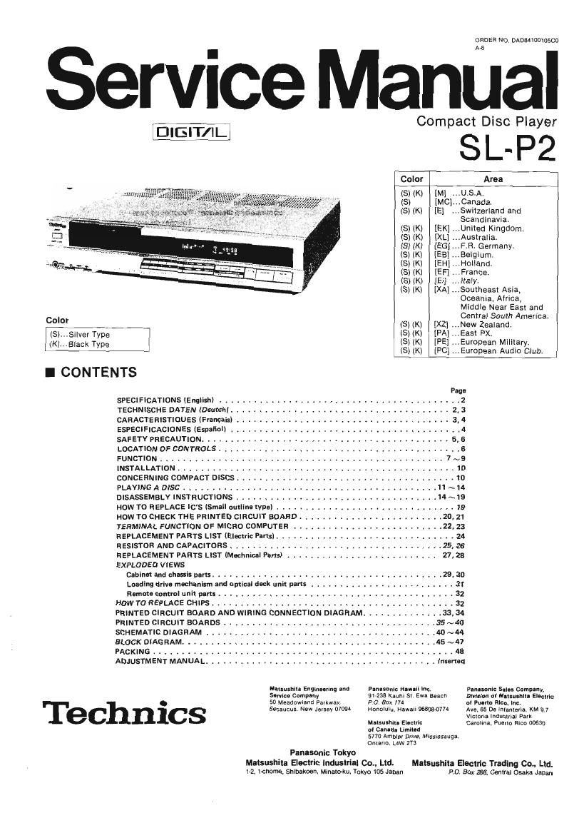
Technics SLP 2 Service Manual

This is the 70 pages manual for Technics SLP 2 Service Manual.
Read or download the pdf for free. If you want to contribute, please mail your pdfs to info@audioservicemanuals.com.

Page: 1 / 70
left right
Technics SLP 2 Service Manual

Extracted text from Technics SLP 2 Service Manual (Ocr-read)


Page 1

Service Ma

mTQ

ORDER NO. DAOM I00105Cfl

Compact Disc Player

SI.- P2

Technics

Area
[Ml ...U.S.A.
.. Canada.
{E} Switzerland and
Scandinavia.
(S) (K) [EK] ...Uniied Kingdom.
(S) (K) [XL] .. Australia.
(8) (K) [EG] .. F.Fl. Germany.
(8) (K) [EB] ...Belgium.
(5) (K) [EH] ...Holland.
(S) (K) [EH France.
(S) (K) [El] ...|la|y.
(S) (K) [XA] ...Soulheasl Asia,
Oceania, Africa.
Middle Near Easl and
Central South America.
00' i (S) (K) 1le ...New Zealand.
(S)...Silver Type (S) (K) [PA] ...Easl PX,
(K)...Black Type (S) (K) [PE] ...Eulopean Military.
7% (S) (K) [PC] European Audio Club.
I CONTENTS
Page
SPECIFICATIONS (English) .......................................... 2
TECHNISCHE DATEN (Damch) . . . . . . .

CARACTERISTIOUES (Francais) .
ESPECIFICACIONES [EspafioII . .

SAFETY PRECAUTION ............... . .................... . . .
LOCATION OF CONTROLS ....................................
FUNCTION .............. . . . .
INSTALLATION . . .............................................. 10
CONCERNING COMPACT DISCS ...................................... Ifl
PLAYINGADISC.. .. . . .. .. 11~14
DISASSEMBLY INSTRUCTIONS ................................... 14 ~19
HOW TO REPLACE IC'S (Small outline type) ............. . ..... . ..... . ..... 19
HOW TO CHECK THE PRINTED CIRCUIT BOARD 20. 21
TERMINAL FUNCTION OF MICRO COMPUTER . .22, 23
REPLACEMENT PARTS LIST [Electric Pam}. . . . . . . 24
RESISTOR AND CAPACITORS ....... . . . . . . . . . . . . 25,26
REPLACEMENT PARTS LIST (Machnical Pans) .......................... 27, 28
EXPLODED VIEWS

Cabinm and chassis parts. . ..... . ............................ .29, 30

Loading drive mechanism and amical deck unit pans ......... . 31

Human control uni pm: ................... . . . . . . , . .32
HOW TO REPLACE CHIPS ................................... . ..... 32
PRINTED CIRCUIT BOARD AND WIRING CONNECTION DIAGRAM .............. 33, 34
PRINTED CIRCUIT BOARDS ........................ . . ..... 35~ 40
SCHEMATIC DIAGRAM ........................................ 40 ~44
BLOCK DIAGRAM. . ..... . .................................... 45 ~47
PACKING ........ A. .. .. .. ..... 48
ADJUSTMENT MANUAL ........................................ inserted

Fan-sonic Hawaii Inc.
91.233 Kauhi Sl. Ewa Beach
P O Box 774

Honolulu. Hawaii 9680807

Mmusnlr- Englnming and
Scale: Company

50 Meadowland Parkway.
Secaucus. New Jersey 0709

Mtlsushlu Emlnc
oI Clnudl leIIlfl
577D Ambler Drive. Miss-ssauga.
Onlarrv. LdW 273
Panasonic Tokyo

Malsushim Electric industrial 00., Ltd.
1-2, 1chome, Shlnakoen, Minatcrku. Tokyo 105 Japan

Pun-sonic Sal-a Company,
DIVISION OI MDISMIIIIII EIDCIIII:
OI Plum: Rica. Inc.

Ave. 65 D8 lnianlena. KM 9,7
Vlcmna Industrial Park
Cawlma, Puerlo Rico 00630

Malsushila Electric Trading 00.. Lid.
PO. Box 288, Genital Osaka Japan

Page 2

English
- - - Specifications are subject to change without notice for further improvement.
Speclflcaflons Weight and dimensions shown are approximate
I General Display: (Digital display)»

Power supply:

Power consumption:
Output voltage:
Output Impedance:
Load impedacne:
Dimensions

(W X Dx H):

Weight:

I Audio

No. of channels:
Frequency response:
Dynamic range:

S/N ratio:

Channel separation:
Wow and flutter:

I Signal Format
Sampling frequency:
Correction system:
D-A conversion:

I Pickup

Type:

Light source:
Wavelength:

Search modes:

F eatu res :

Total harm. distortion:

For USA. and Canada:
120V, AC 60 HZ

For others: ~110~120VI
220~240V, 50/60 Hz

30 Walls

2 volts (at 0 dB)

3300

more than 5 k0

43x33.4x8.2 cm
(165/15"><37/32")
When disc holder Is opened
45:90m(18/is)(D)

5.1 kg (ii 2lbs)

2(lett and right stereo)
4-20,000 Hz:0.5 dB

more than 96 dB

more than 95b dB

less than 0,003% (1 kHz. 04:18)
more than 90 dB

below measurable limit

44.1 kHz
Technics Super Decoding Algorithm
16-bit linear

Astigma 3-beam
Semiconductor laser
300 run

I Functions (FeaturES)

Manual search.

Track skip,

Music scan

Track program

Auto play.

Track random access,

Index random access:
Programmable play,

(15 track memory),

Forward skip,

Reverse skip,

Forward search (track and index),
Reverse search (track and index),
Repeat play,

A'B repeat play.

Music scan

Operation buttons:

Disc loading:

No. of tracks,

Total playing time (min, sec).
Track being played,

Elapsed playing time,
Remaining time,

Index not,

(Segment display),

No: of tracks,

Track being played,
Programmed tracks

Basic buttonsi7

Program buttons-1 2

Music scan button-1
Repeat button-1

A-B repeat buttonA-1

Main time buttonii
Motor-driven horizontal type

Headphone output level: Max. 80 mV (adjustable): 320

Infrared Remote Control Unit:

Remote control
functions:

Dimensions
(waxo):
Batteries:

Basic buttons-6
Program buttonsniz
Music scan button-t
Repeat button-i
A-B repeat button-1
Recall button-i

5.6X13.5Xlr5cm
UM-4 AAA" batteries or IEC R03 or
equivalent (1.5 Vx2)

Deutch

I Allgemeines
Stromversorgung:
Strombedart:
Ausgangsspannung:
Ausgangsimpedanz:
Lastimpedanz:
Ahmessungen:
(BXTXH)

Gewicht:

TECHNISCHE DATEN

~110-120/220-240 VI 50/60 Hz
30 Wall

2 Volt (bei 0 dB)

3300

mehrals 5 k0

43xa3,4><8.2cm

Wenn Disc-Halter often Isl
45,9 cm (T)

5,! K9

I Audio
Kanalanzahl:
Frequenlgang:
Dynamikbereicn:
Rauschabstand:
Totalklirrverzerrung:
Kanaltrennung;
Gleichlaulschwan-
kungen:

Anderungen der technischen Daten vorbehalten.
Die angegebenen GEWIChlS- und Abmessungsdaten sind ungefahre Wertet

2 (links und rechls, Stereo)

4~20 000 Hzi0,5 dB

mehr als 96 dB

mehrals 96 dB

wenlger als 0,0011% (1 kHz. 0 dB)
mehr als 90 dB

unterhalb Messbarkeit

Page 70

Eie de suspensibn T
A


Engranaje
gufa

Fig. A Sefiai RF!

No tacar

Fig. B Vista inferior de urfiad transversal

4. Ajuste de rejilla

1. Coloque el Disco de prueba sobre el plato giradiscos y
if fije con el iman.
E 2. Conecte el osciloscopio come sigue: Senal RF
in
w BARRIDO ...... 2m. 3" CH1
CH1 .......... TJ402 (P.C.B. 01)
CH2 .......... C164 en P.C.B. 03 (Perno 17 de
lC104).
3. Aphque energia a la umdad y selecmone la modalidad de Mar N
Interpretacmni en CH2
4. Si se presentan sefial RF y marca N, no se requiere
ningtm ajuste como en la Fig. A mama N
SI no se presentan senal RF y marca N , efectue el Fig. A Safial RFy marca"N
past: 5.
5. Insane I: lhsirzjarniiama' d: aisls'te de rejijjia :entro dei Fonocapmréptim mam giradiscos
agu1ero e a o izquler o e cuerpo e onoca tor
P a /

éptico come mostrado en la Fig. B.

8. Haga girar la herramienta de aiuste de rejilla hacia ia Eie de
direcha o izquierda hasta que la marca N as losusnensm
més nl'tida y se obtenga Ia méxima sefial RF. rfi [:>
-_ ll Pane front-1i
de deck


\ lnsertar Ia herrarniemo

L- de ajuste de reiilla

Iii

Fig. B Vista lateral izquierda de unidad transversal

5. Alineamiento eléctrico de unidad principal. Siga el ajuste, refiera a la péginas 15 ~ 18.

6. Comprobacién dei P.C.B. 03

5 L

* Después de! ajuste, ordene todos Ios componentes para Janua-EHQLW

J que estén pianos sabre P.C.B. 03, y rearme sobre la pflnos G a _ P101 Form

1 unidad transversal. ggwgonemss Q P102 componentes
" Una vez se ha montado el P.C.B. 03, asegurese de que 9'3"


Ia parte inferior del fonocaptor no interfiere con nin- dgcs
guno de ios oomponentes. ofigg
For In canto, asegfirese de que los surcos en los hordes E'g pone,
externos del disco son aocesibles. Ponar camponantes
components: pianos
pianos \\
_. 32 _ Printed in Japan

841008800 ® AN