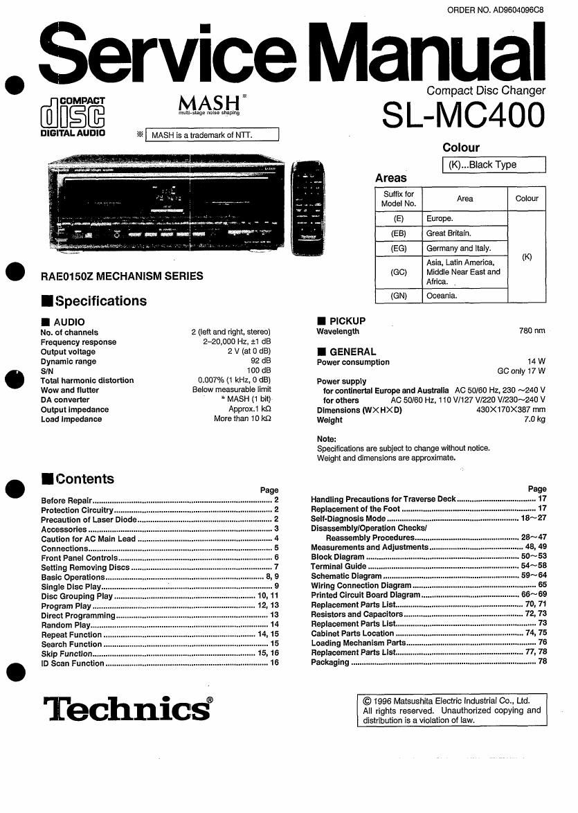
Technics SLMC 400 Service Manual

This is the 69 pages manual for Technics SLMC 400 Service Manual.
Read or download the pdf for free. If you want to contribute, please mail your pdfs to info@audioservicemanuals.com.

Page: 1 / 69
left right
Technics SLMC 400 Service Manual

Extracted text from Technics SLMC 400 Service Manual (Ocr-read)


Page 1

ORDER NO. AD960409608

Service Manual

@GDMPAGT

Mum 'IagAe noise Ssthing

3K MASH' Is a trademark of MT.

DIGITAL AUDIO

RAE01502 MECHANISM SERIES

I Specifications
I AUDIO

No. of channels
Frequency response

2 (left and right, stereo)
2-20,000 Hz, :1 dB

Output voltage 2 V (at 0 dB)
Dynamic range 92 dB
SIN 100 dB

Total harmonic distortion
Wow and flutter

DA converter

Output impedance

Load impedance

0.007% (1 kHz, 0 dB)
Below measurable limit
' MASH (1 bit)
Approx.1 in

More than 10 k9

I Contents

Before Repair .......
Protection Circuitry
Precautlon of Laser Diode
Accessories ..
Caution for AC Main ea
Connections ............
Front Panel Control
Setting Removing Discs
Basic Operations.
Single Disc Play...
Disc Grouping Play
Program Play
Direct Programming
Random Play....

Pag

mwNmUI-hWMNMW

Skip Function...
lD Scan Function .

Technics®

Compact Disc Changer
S L- M C4 0 0
Colour
Areas
5:32: :5; Area Colour
(E) Europe.

(EB) Great Britain.
(EG) Germany and Italy.

Asia, Latin America, (K)
(GC) Middle Near East and
Africa. .
(GN) Oceania.
I PICKUP .
Wavelength 780 nm
I GENERAL
Power consumption 14 W
60 only 17 W
Power supply

for continertal Europe and Australia AG 50/60 Hz, 230 ~240 v

for others AC 50/60 Hz, 110 V/127 v1220 Vl230~240 V
Dimensions (WX HX D) 430x170><387 mm
Weight 7.0 kg
Note:

Specifications are subject to change without notice.
Weight and dimensions are approximate.

Handling Precautions for Traverse Deck
Replacement of the Foot .
Self-Diagnosis Mode
Disassemblleperation Checks]

Reassembly Procedures"

Measurements and Adjustment 48, 49
Block Diagram 50~53
Terminal Guide 54~58
Schematic Diagram .. 59~ 64

Wiring Connection Diagram
Printed Circuit Board Diagram
Replacement Parts List ........
Resistors and Capacitors
Replacement Parts List
Cabinet Parts Location
Loading Mechanism Part ..
Replacement Parts List 77, 78
Packaging ..................

©1996 Matsushita Electric industrial Co., Ltd.
All rights resewed. Unauthorized copying and
distribution is a violation of law.

Page 2

SL-MC400

A WARNING
This service information is designed for experienced repair technicians only and is not designed for use by the general public. It
does not contain warnings or cautions to advise non-technical individuals of potential dangers in attempting to service a product.
Products powered by electricity should be serviced or repaired only by experienced professional technicians. Any attempt to ser-
vice or repair the product or products dealt with in this service information by anyone else could result in serious injury or death. .

IBefore Repair

(1)Tum off the power supply using a 109 , 10 W resistor, connect both ends of power supply capacitors (012, 021, 022) in order to discharge the
voltage.

(2) Before turning the power supply on, after completion of repair, slowly apply the primary voltage by using a power supply voltage controller to
make sure that the consumed current at 50 Hz in NO SIGNAL mode should be shown below with respect to supply voltage 240 Vl110 V/120

Vl220 V/230~240 V.
Power supply voltage AC 240 V AC 110 V AC 120 V AC 220 V AC 230~240 V
Consumed current 50 Hz 30~45 mA 80~100 mA 70~90 mA 30~50 mA 35~55 mA

IProtection Circuitry

The protection circuitry may have operated if either of the following conditions is noticed:
~x~ No sound is heard when the power is switched ON.
*Sound stops during a performance. .
The function of this circuitry is prevent circuitry damage if, for example, the positive and negative speaker connection wires are shorted, or it
speaker systems with an impedance less than the indicated rated impedance of this unit are used.
If this occurs, follow the procedure outlined below:
1. Switch OFF the power.
2. Determine the cause of the problem and correct it.
3. Switch ON the power once again.
Note:

When the protection circuitry functions, the unit will not operate unless the power is first switched OFF and then ON again.

CAUTION! .
THIS PRODUCT UTILlZES A LASER.

USE OF CONTROLS OR ADJUSTMENTS OR PERFORMANCE OF PROCEDURES OTHER THAN THOSE SPECIFIED HEREIN MAY
RESULT IN HAZARDOUS RADIATION EXPOSURE.

IPrecaution of Laser Diode

CAUTION: This product utilizes a laser diode with the unit turned on", invisible laser radiation is emitted from the pickup .
lens.
Wave length: 780 nm
Maximum output radiation power from pickup: 100 pWNDE

Laser radiation from the pickup lens is safety level, but be sure the followings:

1. Do not disassemble the optical pickup unit, since radiation from exposed laser diode is dangerous.
2. Do not adjust the variable resistor on the pickup unit. It was already adjusted.

3. Do not look at the focus lens using optical instruments.

4. Recommend not to look at pickup lens for a long time.

ACHTUNG: Dieses Produkt enthalt eine Laserdiode. lm eingeschalteten Zustand wird unsichtbare Leserstrahlung von der
Lasereinheit abgestrahlt.

Wellenlénge: 780 nm
Maximale Strahlungsleistung der Lasereinheit: 100 pWNDE

Die Strahlung an der Lasereinheit ist ungefahrlich, wenn folgende Punkte beachtet werden: .

1 Die Lasereinheit nicht zerlegen, da die Strahlung an der freigelegten Laserdiode gefahrlich ist.
2. Den werkseitig justierten Einstellregler der Lasereinhit nicht verstellen.

3. Nicht mit optischen Instrumenten in die Fokussierllnes blicken.

4 Nicht L'iber langere Zeit in die Fokussierllnes blicken.

_2_

Page 22

SL-MC400J

Check of basic CD operation

[With power supply OFH
1 Place one disc in stacker. For example, place a disc in slot No.30.

POWER Press power

[CHECKING DISCS] scrolls across the display, and
the number of the slot containing the disc Is displayed.

Press either («4 orm) until
3 EVE] you reach the desired track. _ _

I44 : You can skip backward. _I I I

»i : You can skip forward. D _I U Disc
:1 Track number at the
m'K playing position.

4 Press PLAY (>). '
i 7 Fl . .
- > -- Pia Indicator
:> J LI ms: y

E, 1:] .E ,'-- Elapsed play time
m MIN SEE

EIZ] [In the play or pause mode]
5 i Press and hold « or »
« : you can search backward.
» : You can search forward.

E % Press PAUSE ( u ). E>
7 Press STOP( l ).
j g) :>

Result Handling

In accordance with the buttons operated in Self-diagnosiszm mode ,

No abnormalities in any operation all operation buttons (32 buttons) except the DISC ENTER button are normal.

Perform PROGRAM and other operation.

Ill uminates

Total number of tracks Total playing time

Fails to play or

. Perform servo adjustment mode (p26, 27).
play performance IS poor.

Failure of operation other than play. Check between button which does not work and servo module.
. Check for FFC catching of the CPU.
(Example) [3°95 01 5'? "mks- Check for bending of the traverse deck worm gear.

_22,

Page 26

SLfMC400 7

-elf-diagnosis Servo adjustment mode

This function shows the operating status of the servo system circuits (focus, tracking. CLV) on the FL display.

The results of automatic adjustment of the servo circuit are also displayed, using error codes.
Check when assembled Check while disassembled

Load CD into stacker.
Set to S/M p.33 state.
Turn OFF the power button.
Perform To independently operate the

Turn ON the power button while
simultaneously pressing STOP ( I ), traverse deck on p.23.

PAUSE ( n ) and PLAY (» ).
PAUSE

Press PLAY ( > ), and after playing for
10 seconds, press PAUSE ( ll ).

.

6 mfifitfimfi - ~

STOP PLAY

H" level FO TR CLV

How to read FTC.

L level F0 TR CLV

Press STOP ( I ).
H" level

- FO system NG

1'- TR system NG

Error code L SP mortor NG
FO: Focus
TR: Tracking
93" Halldllng CLV: CLV servo
It: _ U U Normal
th d' l ,
aid: 201 Refer to p.27 to remedy.

_26_