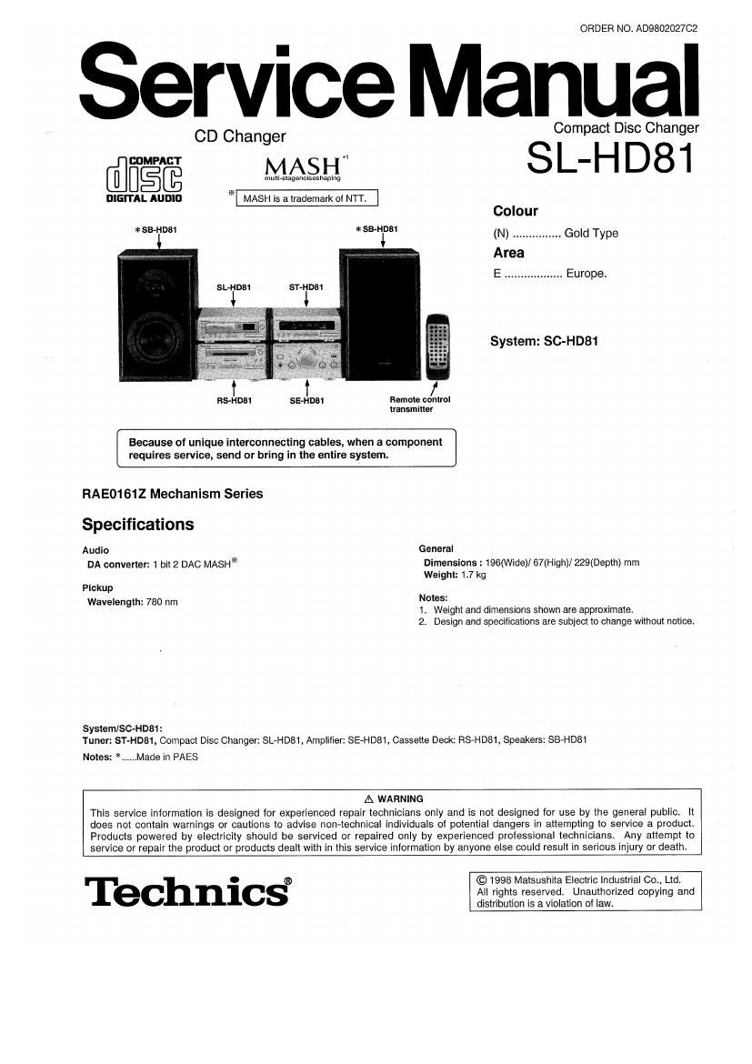
Technics SLHD 81 Service Manual

This is the 50 pages manual for Technics SLHD 81 Service Manual.
Read or download the pdf for free. If you want to contribute, please mail your pdfs to info@audioservicemanuals.com.

Page: 1 / 50
left right
Technics SLHD 81 Service Manual

Extracted text from Technics SLHD 81 Service Manual (Ocr-read)


Page 1

ORDER NO. AD9802027CZ

Service Manual

CD Changer Compact Disc Changer

[WEE MASH SL-H D 81

DIGITAL AUDIO X MASH is a trademark of NTT.

Colour

*SB-HD81 *SBHDB (N) .. .. Gold Type
Area
E .................. Europe.

ST-HDB1

System: SC-HD81

Rs-HD81 sE-HD81 Remote control
transmitter

Because of unique interconnecting cables, when a component
requires service, send or bring in the entire system.

RAEO161Z Mechanism Series

Specifications
AUUiO General
DA converter: 1 bit 2 DAC MASHX Dimensions : 196(Wide)/ 67(High)/ 229(Depth) mm
Weight: 1.7 kg
Pickup
Wavelength: 780 nm Notes:

1. Weight and dimensions shown are approximate.
2. Design and specifications are subject to change without notice.

SysternlSCvHDS1 :
Tuner: ST-HDat, Compact Disc Changer: SL~HD81, Amplifier: SE-HD81, Cassette Deck: RSeHD81, Speakers: SB-HDBt

Notes: *......Made in PAES

A WARNING
This service information is designed for experienced repair technicians only and is not designed for use by the general public. It
does not contain warnings or cautions to advise non-technical individuals of potential dangers in attempting to service a product.
Products powered by electricity should be serviced or repaired only by experienced professional technicians. Any attempt to
service or repair the product or products dealt with in this service information by anyone else could result in serious injury or death.

© 1998 Matsushita Electric industrial Co., Ltd.

T 0 ®
eChnlcs All rights reserved. Unauthorized copying and
distribution is a violation of law.

Page 2

SL-HD81

I Contents

Precautlon of Laser Diod
Location of Controls
Handling Precautions for raverse Deck.
Operation Checks and Main Component
Replacement Procedures
Replacement of the Foot
Error Code Display and Servo Adjustment Function
Measurements and Adjustments .


NOTES:

Block Diagram .....
Wiring Connection Diagram
Schematic Diagram
Printed circuit Board Diagram
Terminal Function of We
Replacement Parts List
Cabinet Paris Location
Loading Mechanism Parts Location .


ORefer to the service manual for Model No. ST-HD81 (ORDER No. AD980202662) tor information on Installation " and connections".
"Refer to the service manual for Model No. SE-HD81 (ORDER No. AD980202862) for information on Accessories.

IPrecaution of Laser Diode

CAUTION:
lens.
Wave length: 780 nm

This product utilizes a laser diode with the unit turned "on, invisible laser radiation is emitted from the pickup

Maximum output radiation power from pickup: 100 uWNDE

Laser radiation from the pickup lens is safety level, but be sure the followings:

1. Do not disassemble the optical pickup unit, since radiation from exposed laser diode is dangerous.
2. Do not adjust the variable resistor on the pickup unit. It was already adjusted.

3. Do not look at the focus lens using optical instruments.

4. Recommend not to look at pickup lens for a long time.

ACHTUNG:
Lasereinheit abgestrahlt.

Wellenlange: 780 nm

Disses Produkt enthélt eine Laserdiode. Im eingeschalteten Zustand wird unsichtbare Leserstrahlung von der

Maximale Sirahlungsleistung der Lasereinheit: 100 uWNDE

Die Strahlung an der Lasereinheit ist ungefahrlich, wenn folgende Punkte beachtet werden:

1. Die Lasereinheit nicht zerlegen, da die Strahlung an der ireigelegten Laserdiode gefahrlich ist.

2.
3.
4

Den werkseitig justierten Einstellregler der Lasereinhit nicht verstellen.
Nicht mit optischen lnsirumenten in die Fokussierlines blicken.
Nicht fiber tangere Zeit in die Fokussierlines blicken.

Back side
0 N

CLASS 1
LASER PRODUCT

LUOKAN 1 LASERLAITE
KLASS 1 LASER APPARAT

Upper side

W mm use» mum lilllfll om

Wt. 5
VARO!


mm

VARNINS

ma m

muse W
VDRSICHT W SSW WNW


CAUTION!
THIS PRODUCT UTILIZES A LASER.

USE OF CONTROLS 0R ADJUSTMENTS OR PERFORMANCE OF PROCEDURES OTHER THAN
THOSE SPECIFIED HEREIN MAY RESULT IN HAZARDOUS RADIATION EXPOSURE.

_2_

Page 14

SL-HD81

G

Washer-©

U

I Remove the washer and load main gear. I

I Release the 1 claw, and then pull the tray unit. I

U

with pressing the claw In the direction of arrow,
pull the sub tray one by one.

- Tray base has 5 sub trays. When mounting the
sub tray to the tray unit, the mounting order is
not cared.

G

m I Remove the elevation cam.

Step cam (Fl) ass'y

Slide the step cam (R) assy in the direction
of arrow ® and align It with the slots, then
remove the step cam (R) assy in the direction
of arrow @.

-14-

Page 21

SL-HDB1

Gear cover

Step cam (L) assy

Boss - I
.\ I

Hole

%

@- M tray gear
!

Mechanism
chassis ass

Tilt the disc stopper in the
direction oi arrow

\éfi

Mechanism chassis ass'y

Disc sto pper

I Tighten the screws (0). I

I Install the M tray gear.

'v

G

Install the gear cover. I

The claws (2 points) must be latched.

Mate the marking toward the front side
(Refer to figure below.)


M tray gear

[From side]

Marking

Align the slots of step cam (L) assy with the
hooks of mechanism chassrs assy, and then
install the step cam (L) assy.

When installing the step cam (L ass'y to the
mechanism chassis assy, instal it with pressing
the switch boss in the direction of arrow.

G

Temporarily install the stopper spring on the
hook of disc stopper.

Disc stopper

Stopper spring

Align the boss of disc stopper with the hole of
mechanism chassis assy

_21_