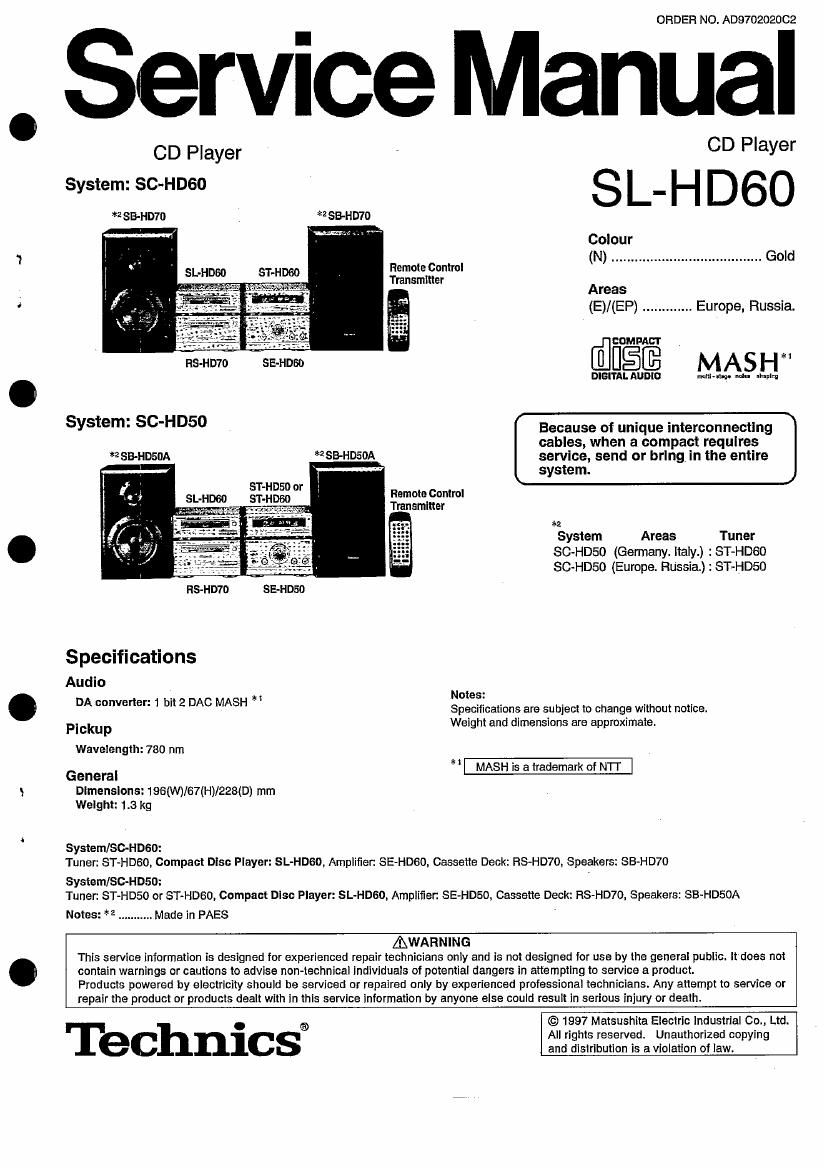
Technics SLHD 60 Service Manual

This is the 36 pages manual for Technics SLHD 60 Service Manual.
Read or download the pdf for free. If you want to contribute, please mail your pdfs to info@audioservicemanuals.com.

Page: 1 / 36
left right
Technics SLHD 60 Service Manual

Extracted text from Technics SLHD 60 Service Manual (Ocr-read)


Page 1

ORDER NO. AD970202002

, Service Manual

CD Player - CD Player
System: SC-HDGO S _
SB-ND) *ZSB-HD7D L H D60
m Colour


(N) ....................................... Gold
Remote Control
Transmitter
Areas
(E)/(EP) ............. Europe, Russia.
_ '- » EDMPAUI'
disc MASH
DIGITAL AUDIO multl-IIIDO Min mm
SVStem: SCHD50 Because of unique interconnecting
cables, when a compact requires
*ZSB-HosuA SB-HDSOA service, send or bring in the entire
' " system.
SFHDSD or Remote Control
Transmitter
*2
System Areas Tuner

SC-HDSO (Germany. ltaly.) : ST-HDSO
SC-HD50 (Europe. Russia.) : ST-HDSD

HS-HWD SE-HD50

Specifications
Audio

DA converter: 1 bit 2 [mo MASH "35

Specifications are subject to change without notice.
Pickup Weight and dimensrons are approXImaie.

Wavelength: 780 nm

* MASH is a trademark of Nll

General
Dimensions: 196(W)/67(H)/228(D) mm
Weight: 1.3 kg

System/SC-HDGO:
Tuner: ST-HDGO, Compact Disc Player: SL-HDGO, Amplifier. SE-HDGO, Cassette Deck: RS-HD'IO, Speakers: SB-HD70

Systom/SG-HD50:
Tuner: ST-HDSO or ST-HDGO, Compact Disc Player: SL-HDGO. Amplifier: SE-HDSO, Cassette Deck: RS-HD70, Speakers: SB-HDEOA

Notes: 3 2 ........... Made in PAES

AWARNING.
This service information is designed for experienced repair technicians only and is not designed for use by the general public. It does not
contain warnings or cautions to advise non-technical individuals of potential dangers in attempting to service a product.
Products powered by electricity should be serviced or repaired only by experienced professional technicians. Any attempt to service or
repair the product or products dealt with in this service information by anyone else could result in serious injury or death.

© 1997 Matsushita Electric industrial Co., Ltd.

0
® All rights reserved. Unauthorized copying
ec nlcs and distribution is a violation of law.

Page 2

SL-HDBD

I Contents

Handling Precautions for Traverse Deck
Precaution of Laser Diode
Location of Controls ..
Listening to Compact
Operation Checks and

Main Component Replacement Procedure
Schematic Diagram
Type Illustration of i0 5, Transrstors and
Wiring Connection Diagram
Printed Circuit Board Diagram
Terminal Function of IC's .

iaC

NOTE:


Error Code Display and Servo Adjustment Function
To Supply Power Sourc
Block Diagram
Troubleshooting Gun 9.
Replacement Parts List (Electrical)
Resistors and Capacitors
Cabinet Parts Location.
Loading Mechanism Parts use to
Replacement Parts List

(Cabinet, Loading Mechanism and Jig/Tool) ..................................... 36

Refer to the service manual for Model No. SE-HDGO (ORDER No. AD970102202) and Model No. SE-HDSO (ORDER No.
AD970101702) for information on Accessories", "Installation", Connections" and "Packaging".

CAUTION:
THIS PRODUCT UTiLiZES A LASER.

USE OF CONTROLS OR ADJUSTMENTS OR PERFORMANCE OF PROCEDURES OTHER THAN THOSE

SPECIFIED HEREIN MAY RESULT IN HAZARDOUS RADIATION EXPOSURE.

l Handling Precautions for Traverse Deck

The laser diode in the traverse deck (optical pickup) may break down due to potential difference caused by static electricity of clothes or human body.
So, be careful of electrostatic breakdown during repair of the traverse deck (optical pickup).

0 Handling of traverse deck (optical pickup)

1. Do not subject the traverse deck (optical pickup) to static slectncity as it is

extremely sensitive to electrical shock.

2. To protect the laser diode against electrostatic breakdown, short the flexible

board (FFC board) with a clip or similar object.

3. Take care not to apply excessive stress to the flexible board (FFC board).
4. Do not turn the variable resistor (laser power adjustment). it has already been

adjusted.

O Grounding for electrostatic breakdown prevention
1. Human body grounding

Use the anti-static wrist strap to discharge the static electricity from your body.

2. Work table grounding

Put a conducive material (sheet) or steel sheet on the area where the traverse

deck (optical pickup) is placed, and ground the sheet.

Caution:

The static electricity of your clothes will not be grounded through the wrist strap.
80, take care not to let your clothes touch the traverse deck {optical pickup).

Caution when Replacing the Traverse Deck:

FFC board Lens (Do not touch)

Wendie it carefully)


Variable resistor

No. @ (GND) pin (Do ncttum)

No. @ (LD) pin


Wrist strap '
(Anti-static bracelet) /

iron plate or some metals to
conduct electricity

The traverse deck has a short point shorted with solder to protect the laser diode against electrostatic breakdown. Be sure to remove the solder from

the short point hetore making connections.

Page 7

SL-HDGO

2. Checking for the servo P.C.B.

- Follow the m] - GM? of the item 1 in checking
procedure for each P.C.B. on pages 5 and 6.

Release the 4 claws, and then Loading unit.
remove the loading unit.

' Check the servo P.C.B. as shown below.


Upset the loading unit.

Reinstall the front panel assy
to the main unit.

I Main Component Replacement, Procedures

1. Replacement for the traverse deck assy

. . . 3
- Follow the @I ~ M3 oi the item 1 in checking -ve the loading unit.

procedure for each P. C. B. on pages 5 and 6.

- Follow the [EM] EB of the Item 2' in checking
procedure for each P C. B. on page 7.

Pull out the FFC.

Remove the connector (CN401).