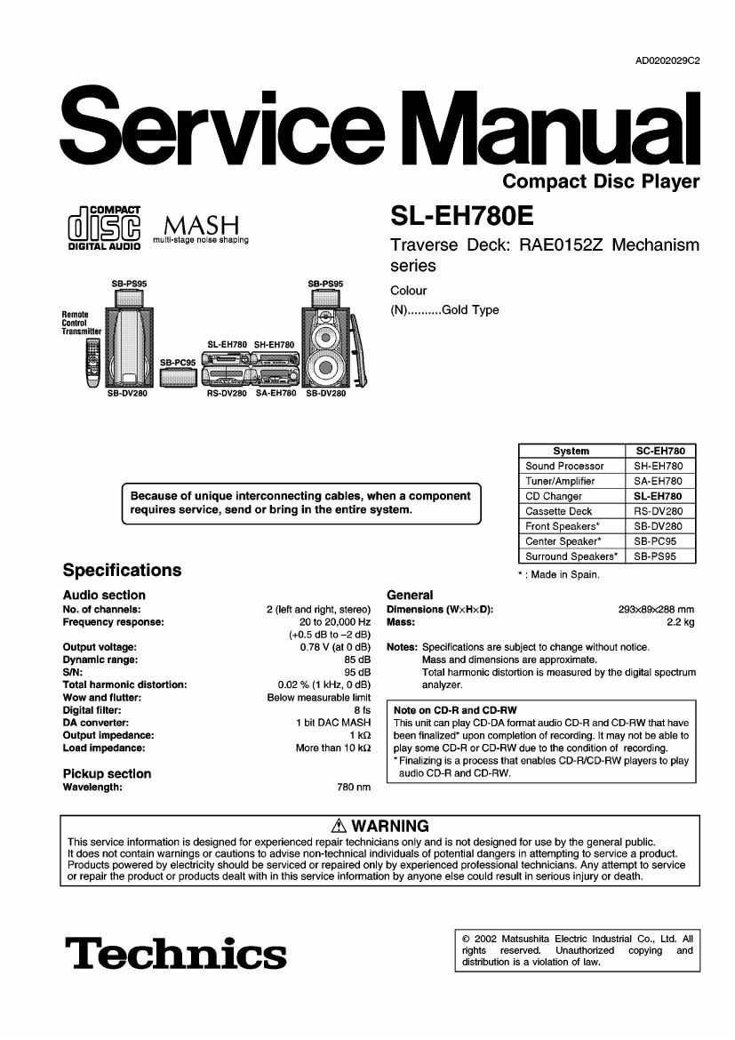
Technics SLEH 780 E Service Manual

This is the 41 pages manual for Technics SLEH 780 E Service Manual.
Read or download the pdf for free. If you want to contribute, please mail your pdfs to info@audioservicemanuals.com.

Page: 1 / 41
left right
Technics SLEH 780 E Service Manual

Extracted text from Technics SLEH 780 E Service Manual (Ocr-read)


Page 1

AD0202029C2

Service Manual

COMPAB'I'

MAS H

mulll-sta e noise she in
DIGITAL AUDIO 9 p 9

SB-PSQS

SB


Remote
Control
Transmitter

Compact Disc Player

SL-EH780E

Traverse Deck: RAEO152Z Mechanism
series

Colour
(N) .......... Gold Type

Because of unique interconnecting cables, when a component CD Changer
requires service, send or bring in the entire system.

Specifications

Audlo section

No. of channels: 2 (left and right, stereo)

Frequency response: 20 to 20,000 Hz

(+0.5 dB to -2 dB)
Output voltage: 0.78 V (at 0 dB)
Dynamic range: 85 dB
SIN: 95 dB

Total harmonic distortion:
Wow and flutter:

0.02 % (1 kHz, 0 dB)
Below measurable limit

Digital filter: 8 ts
DA converter: 1 bit DAG MASH
Output Impedance: 1 kn

Load impedance: More than 10 kt)
Pickup section

Wavelength: 780 nm

System SC-EH180
Sound Processor SH-EH780
Tuner/Amplifier SA-EH780
SL-EH780
Cassette Deck RS-DV280
Front Speakers* SB-DV280
Center Speaker" SB-PCQS
Surround Speakers* SB-PS95
" : Made in Spain.
General
Dimensions (WxHxD): 293x89x288 mm
Mass: 2.2 kg

Notes: Specifications are subject to change without notice.
Mass and dimensions are approximate.
Total harmonic distortion is measured by the digital spectrum
analyzer.

Note on CD-R and CD-Ftw

This unit can play CD-DA format audio CD-R and CD-FlW that have
been finalized upon completion of recording. It may not be able to
play some CD-R or CD-RW due to the condition of recording.

* Finalizing is a process that enables CD-Ft/CD-RW players to play

audio CD-Fl and CD-RW.

A WARNING

This service information is designed for experienced repair technicians only and is not designed for use by the general public.

It does not contain warnings or cautions to advise non-technical individuals of potential dangers in attempting to service a product.
Products powered by electricity should be serviced or repaired only by experienced prolessional technicians. Any attempt to service
or repair the product or products dealt with in this service information by anyone else could result in serious injury or death.

Technics

© 2002 Matsushita Electric Industrial Co., Ltd. All
rights reserved. Unauthorized copying and
distribution is a violation of law.

Page 2

CONTENTS

Page

1 Note -------------- - - ------- 3
2 Handling Precautions tor Traverse Deck ................................ 3
2.1. Handling of traverse deck (optical pick-up) ................... 3

2.2. Grounding tor electrostatic breakdown prevention ------------ 3

3 Precaution of Laser Diode .4
4 Location of Controls ------ i 4
5 Operation Checks and Component Replacement Proceduress
5.1. Checking for the main P.C.B. ......................................... 5
5.2. Checking for the operation P.C.B. ................................... 5
5.3. Checking for the CD servo P.C.B. ---------
5.4. Replacement for the traverse deck ass ab
5-5. Replacement for the disc tray ...............

1 0
5.6. Disassembly and reassembly for mechanism base drive

unit ------------------------------------------------------------------------------ 12

5.7. Replacement for the motor ass 5&1 ---------------

6 Error Code Display and Servo Adjustment Function

6.1. Error code display procedure ----------------------

6.2. Servo adjustment procedure ----------------------------------------- 20


6.3- Error code based on troubleshooting ----------------------------- 21

Page

7 To Supply Power Source ...................................................... 22
8 Schematic Dlagram Notes .................................................... 22
9 Schematic Diagram ............................................................... 23
10 Printed Circuit Board Diagram ---------------------------------------------- 27

11 Type Illustration of lOs, Transistors and Diodes

29
12 Wiring Connection Diagram ---------------------------- 30
13 Block Diagram ---------------------------------------------------------------------- 31
14 Troubleshooting Guide --------------------------------------------------------- 33
15 Terminal Function of ma ------------------------------------------------------ 35
15.1. IC451 (CZBBFD000256):System Control* 35
15.2. IC701 (AN8839NSBE2):Servo Amp '- 35

15.3. IC702 (MN662790RSA1):Servo Processor/Digital Signal
Processor/Digital Filter/D/A converter ---------------------------- 35

15.4. IC703 (AN87398BE2):Focus Coil/Tracking Coil/Traverse
Motor/SpindleMotor Drive
16 Replacement Parts List
17 Cabinet Parts Location
18 Loading Unit Parts Location ------------------------------------------------- 41

Page 5

5 Operation Checks and Component Replacement
Procedures

. Check the main P.C.B. as shown below.

I Gear for servicing (as jig) information I

1. This unit has a gear which used for checking items
(Open/close of disc tray, up/down operation of
traverse unit by manually) when servicing. (For gear
information, that is described on the items for
disassembly procedures.)

2. For preparation of gear (for servicing), perform the
procedures as follows.

3. In case of re-servicing the same set, the gear for
servicing may be took off because it had been used.
So, the gear for servicing must be stored.

1. Remove the gear provided with mechanism cover as

shown below.
Cut these ortions to - -
take me 95,, on 5.2. Checking for the operation
P.C.B.
$1 - Follow the (Step 1) - (Step 3) of item 5.1.
(9 (Step 1)
Hexagonal Upset the unit, and then put the
, wrench hexagonal wrench with gear into
Mechanlsm cover the bottom hole to engage the
drive gear.
r ->

2. Insert the hexagonal wrench (2mm) into the gear, and _
then project the tip of wrench for 1~2mm length. (Bottom Side)

Gear Hexa onal wrench
[Part 0. : SZZP11010]

_.I%K:)

1~2mm

(Preparation of gear as jig is completed.)

5.1. Checking for the main P.C.B.

Step 2)

otate the hexagonal wrench with gear in direction
(Step 3) of arrow, and then open the disc tray.

Remove the top cabinet.


(Step 2)
0

. (Step 1)
9 x 4 Disc tray

Page 7

Step 6)

emove the CD changer unit. }
h
,

CD servo P.C.B.

(Step 7)
Rise the CD changer unit.

NOTE:

~ The CD unit should be checked under "PLAY MODE'.

- Do not operate the "DISC change' while the unit is
stayed vertically.

Cable arragement

I Notice for installing the FFC
When connecting the FFC, insert
it straight with nipping the
reinforcement plate by finger.


3})?
Reinforcement

FFC (14PIN) plate

/ FFC (23PIN)

Folding portion

- Hook the FFC to the
ribs (2 portions).

5.4. Replacement for the traverse
deck assy

. Follow the (Step 1) - (Step 3) of item 5.1.
- Follow the (Step 1) - (Step 4) of item 5.2.

(Step 1)
? e X 2
Step 4) . ?
emove the CD .
changer unit. I, I

(Step 3) (Step 2)
Remove the FFC from Remove the FFC from
connector (CN402). connector (CN401).

Page 21

6.3.

Error code based on troubleshooting

- This unit is satisfactory if the error code is E00 and E02 .
~ Before testing, check that the test disc is free of scratches and optical pick-up is clean.

FL error Symptom Probable cause Signal to check Normal voltage and waveform
code values
display Signal Locatlon PLAY STOP
name
E01 Focus and Clocks X1 IN and X2 OUT, power supply MDATA IC702-pin 8 0.3 V 0 V
tracking offset VDD and reset/HST, all on IC702. MCLK IC702-pin 7 PLAY 23 V
adjustments not MDATA, MCLK, MLD and SENSE signals MLD |C702-pin 9 2 9 V
completed in the tc/from mechanism controller. Tl33ms "Ov '
specified time . -. . .
period. /RST |C702-pln 18 2.9 V 2.9 V
X1 IN |C702-pin 58
W WP-p WI WP-P
F433MH1 FaKIJSMHz
X2 OUT |C702-pin 59
2,4Vp-p 2 AVp-p
7:33.8MN2 F=33.8MH1
E03, E05, Disc play unstable Scratches or contaminants on disc FE |C702-pin 32 PLAY 1.7 V
E07, E09, surface. WW
EOB, EOD, Focus and Tracking sen/o circuit (check
EOF waveforms, voltages and part values.) Zmuvm'v-
Spindle driver circuit. TE |C702-pin 33 PLAY 1.7 V
Optical pick-up. 0 NW
2ms. OrWIDIV,
FOD |C702-pin 28 1.7 V 1.7 V
TRD |C702-pin 27 1.7 V 1.7 V
IRFDET |C702-pin 38 0 V 3.3 V
RF TJ701 PLAY 1.0 V
0.7Vp-p
0.5; c.2v1nlv.
STAT |C702-pin 17 3.3 V 0 V
E04, E06, Best Eye (PD Scratches or contaminants on disc FBAL IC702-pin 30 1.7 V 1.7 V
E00, EOE, balance) surface. RF |C701-pin 3 my 1_o v
adjustment not Focus and Tracking servo circuit (check 07v _
completed in the waveforms, voltages and part values.) ' p p
specified time Optical pick-up. 0.5us.o.2VIDIv.
P9"°d- FE |C702-pin 32 my 1.7 v
n le-p
2m n1 WDIV,
OFT lC702-pin as o v o v
E08, EOA Focus and Scratches or contaminants on disc FE IC702-pin 32 my 1.7 V
Tracking gain surface. a WW
adjustment not Focus and Tracking servo circuit (check
completed in waveforms, voltages and part values.) 2" WD'V'
specified time Optical pick-up. TE IC702-pin 33 my 1.7 V
perlod. 0.4Vp-p
Ems. 0.1VIDIV.
OFT lC702-pin as o v o v

21