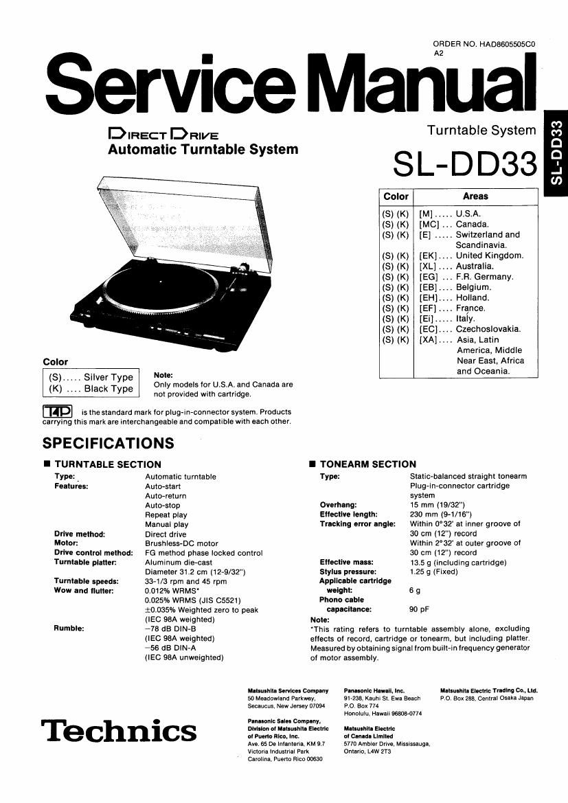
Technics SLDD 33 Service Manual

This is the 11 pages manual for Technics SLDD 33 Service Manual.
Read or download the pdf for free. If you want to contribute, please mail your pdfs to info@audioservicemanuals.com.

Page: 1 / 11
left right
Technics SLDD 33 Service Manual

Extracted text from Technics SLDD 33 Service Manual (Ocr-read)


Page 1

OR DER NO. HA0860550500

Service Manual

DIRECT DRIVE Turntable System

Automatic Turntable System
. SL-DD33

Color Areas

(S) (K) [M] ..... USA.

(S) (K) [MC] . Canada.

(S) (K) [E] ..... Switzerland and
Scandinavia.

(S) (K) [EK].... United Kingdom.
(8) (K) [XL] Australia.

(S) (K) [EG] FR Germany.
(S) (K) [EB].... Belgium.

(S) (K) [EH].... Holland.

(S) (K) [EF] France.

(S) (K) [Ei] ..... Italy.

(S) (K) [EC]. Czechoslovakia.
(S) (K) [XA].... Asia, Latin
America, Middle
Color Near East, Africa

(S) ..... Silver Type g0? d I f U S A d C d and oceama'
nymo as or ...an anaaare
(K) " BlaCk Type not provided with cartridge.
@ is the standard mark for plug-in-connector system. Products
carrying this mark are interchangeable and compatible with each other.
SPECIFICATIONS
I TURNTABLE SECTION I TONEARM SECTION
Type: . Automatic turntable Type: Static-balanced straight tonearm
Features: Auto-start Plug-in-connector cartridge
Auto~return system
Auto-stop Overhang: 15 mm (19/32")
Repeat play Eltectllre length: 230 mm (9-1/16")
Manual play Tracking error angle: Within 0°32' at inner groove of
Drive method: Direct drive 30 cm (12") record
Motor: Brushless-DC motor Within 2°32 at outer groove of
Drive control method: FG method phase locked control 30 cm (12") record
Turntable platter: Aluminum die-cast Ellectlve mass: 13.5 9 (including cartridge)
Diameter 31.2 cm (12-9/32") Stylus pressure: 125 9 (Fixed)
Turntable speeds: 33-1/3 rpm and 45 rpm Applicable cartridge
Wow and flutter: 0.012% WFIMS weight: 6 g
0.025% WRMS (JIS C5521) Phono cable
i0.035"/o Weighted zero to peak capacitance: 90 pF
(IEC 98A weighted) Note:
Rumble: .78 dB DIN-B 'This rating refers to turntable assembly alone, excluding
(IEC 98A weighted) effects of record. cartridge or tonearm. but including platter.
-56 dB DIN-A Measured by obtaining signal from built-in frequency generator
(IEC 98A unweighted) of motor assembly.
Mflwlhiil Service: Company Panasonic Haw-Ii. Inc. Mats-unit: Electric Trading 00.. Ltd.
50 Meadowland Parkway. 9l-2es. Kauhi St. Ewn Beach 9.0. Box 233, Central Osaka Japan
Secaucus. New Jersey 07094 PO. Box 774

Honolulu. Hawaii 96808-0774
. Panasonic Sales Company,
Division at "nu-shit. Electric Mluushlta Electric
C l at Puerto Rico. Inc. at Canad- Limited
Ave. 65 De Inlanteria. KM 9.7 5770 Ambler Drive. Mississauga.

Victoria Industrial Park Ontario. de 2T3
Carolina. Puerto Rico 00630

SL-DD33

Page 2

I CARTRIDGE SECTION

(Except for U.S.A. and Canada)

Type: Moving magnet stereo cartridge
Magnet circuit: AlHaminated core

Frequency response: to Hz~35 kHz

Output voltage: 2.5 mV at 1 kHz, 5 cm/s.

zero to peak lateral velocity

(7 mV at 1 kHz, 10 cm/s. zero to

peak. 45° velocity [DIN 45 500])
Channel separation: 22 dB at 1 kHz

Channel balance: Within 2 dB at 1 kHz
Recommended load
Impedance: 47 kQN1OO kn

Compliance (dynamic): 12><1t)6 cm/dyne at 100 Hz
Stylus pressure range: 1 .25i0.25 9

Weight: 6 g (cartridge only)
Replacement stylus: EPS-SOCS

I CONTENTS

SAFETY PRECAUTION ..... t
LOCATION OF CONTROLS . . 3
DISASSEMBLY INSTRUCTIONS ....................... 3 N 5
CIRCUIT BOARD AND WIRING

CONNECTION DIAGRAM . . t
SCHEMATIC DIAGRAM .....

..................... 6
................... 7,8

I SAFETY PRECAUTION

wth-I

INSULATION RESISTANCE TEST

I GENERAL

Power supply: For USA. and Canada:
AC 120V. 60 Hz
For United Kingdom and Australia:
AC 240V, 50 Hz
For Continental Europe:
AC 220V, 50 Hz
For Others:
AC 110~127l220~240V, 50/60 Hz
Power consumption: 5 W
Dimensions (WXHXD): 430><100><375 mm
(16-15/16"X3-15/16"><14-3/4")
When dust cover is open:
430XS7OX410 mm
(16-15/16"X14»5/32><16-1/B")

Weight: 4.5 kg (9.9 lb.)
Specifications are subject to change without notice for further
improvement.

Weight and dimensions shown are approximate.

Page
BLOCK DIAGRAM ......................... .. 9
MEASUREMENTS AND ADJUSTMENT ..... 1|)

11~13

EXPLODED VIEW . .
REPLACEMENT PARTS LIST. . 14, 15
PACKING ................................... 16

(This safety precaution" is applied only in U.S.A.)

. Before servicing, unplug the power cord to prevent an electric shock.

. When replacing parts, use only manufacturers recommended components for safety.

. Check the condition of the power cord. Replace if wear or damage is evident.

. After servicing, be sure to restore the lead dress, insulation barriers, insulation papers, shields, etc.

t Before returning the serviced equipment to the customer, be sure to make the following insulation resistance test to
prevent the customer from being exposed to a shock hazard.

1. Unplug the power cordand short the two prongs of the plug with a jumper wire.

2. Turn on the power switch.

3. Measure the resistance value with ohmmeter between the jumpered AC plug and each exposed metal cabinet part. such as
screwheads. antenna, control shafts, handle brackets, etc. Equipment with antenna terminals should read between 3M9
and 5.2MQ to all exposed parts. (Fig. A) Equipment without antenna terminals should read approximately infinity to

all exposed parts. (Fig. Bi

Note.- Some exposed parts may be isolated from the chassis by design. These will read infinity.

Anton na
terminal

Exposed
metal
part

Ohm meter

(Fig. A)

Resistance = 3M9-5.2MQ

Exposed
metal
part

Ohmmeter
(Fig. 3)

Resistance = Approx 00

4. if the measurement is outside the specified limits, there is a possibility of a shock hazard. The equipment should be

repaired and rechecked before it is returned to the customer.

_2_

Page 3

I LOCATION OF CONTROLS

Ref. No.
4

How to remove the bottom board

Ref. No. How to remove the start/stop
6 switch knob

Procedure
3 t 4

Soft cloth /

1. Turn over the unit on a soft cloth.
2. Remove the 5 setscrews (0 ~ 9)-

t, Remove the setscrewo.
2. Remove the holder (with knob) in the

Procedure
3 D 4 O 6

direction of the arrows (0, Q).
3. Release the 2 claws.

-10

Holderfi Claws
Knob4§(/%37
9," -_

Note:
When attaching the start/stop knob, do not forget to
attach the spring.

Rel. No. . Ref. No. How to remove the automatic
H w to remove the cueln n .
5 ° 9 k 0b 7 mechanism plate
Procedure ' Remove the setscrewo. Procedure
3 s 4 t 5 3 O 4 t 7

Hinge Hinge
Wu? .. %
[lDl]
45-rpm adaptor /
Record size detector
, /
/ \ A |
Center spindle 1 rm 0 amp
xi Arm rest
Turntable mat
\
\
Turntable platter- \\ Tonearm
\
Turntable base - , Cartridge
' The cartridge for USA.)
Strobe-illuminator/ - -w~ .7. - , and Canada shown here
Pilot lamp LC: FEE is an option.
Speed selector Start/stop switch
Cueing control
Repeat switch
Rel. No . Rel. No
1 How to remove the cartridge 3 How to remove the turntable platter

Procedure 1. Remove the setscrew 0.

1 2 Pull out the cartridge, taking care that
your hand does not touch the stylus
tip.

//

Procedure 1 Open the dust cover and remove the
3 turntable mat.
2. Lift up the turntable platter.

3,. );\y Dust cover
[any 0
fly V V
I, 1 Turntable
qf/ Cartridge mat\
Rel.2 N° How to remove the stylus
Turntable
Procedure 0 Pull out the stylus, taking care not to Platter
2 touch the stylus tip.

Shield plates \_

Stop ro . .

Cuein

1. Remove the stop rod, cueing lever rod and
repeat rod.

2. Remove the 10 screws (0~®).

3. Remove the 2 shield plates.

4. Lift up the automatic mechanism plate.

Note:

When fitting the automatic mechanism plate, check

the following point.

. Turn the main gear until it comes to the no gear
part.