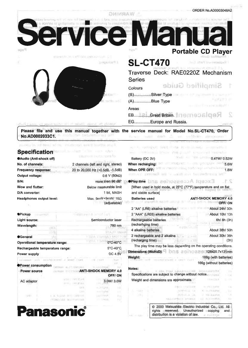
Technics SLCT 470 Service Manual

This is the 39 pages manual for Technics SLCT 470 Service Manual.
Read or download the pdf for free. If you want to contribute, please mail your pdfs to info@audioservicemanuals.com.

Page: 1 / 39
left right
Technics SLCT 470 Service Manual

Extracted text from Technics SLCT 470 Service Manual (Ocr-read)


Page 1

ORDER No.A00003048A2

Service Manual

0.

Portable CD Player
SL-CT470

Traverse Deck: RAE02202 Mechanism
Series


Colours
(S). ..,Si|ver Type
(A). . .Blue Type
Areas
EB .............. Great Britain.
EG .............. Europe and Russia.
Please file and use this manual' together with the service manual for Model No.8L-CT470, Order
No.AD0002033C1.
Specification

.Audio (Anti-shock off)
No. of channels:
Frequency response:
Output voltage:

SIN:

Wow and flutter:

D/A converter:

Headphones output level:

.Pickup
Light source:
Wavelength:

.General

Operational temperature range:
Rechargeable temperature range:
Power supply

OPower consumption
Power source

AC adapter

2 channels (left and right, stereo)
20 to 20,000 Hz (+0.5dB, -1t5dB)

0.6 V (SOkQ)

more than 96 dB
Below measurable limit
1 bit, MASH

Max. 9mW+9le 160
(adjustable)

Semiconductor laser
780 nm

0°040°C
5°C~40°C
DC 4.5V

ANTI-SHOCK MEMORY 4.0
OFF] ON

3.0W/ 3.0W

Panasonic

Battery (DC 3V) 0.47W/ 0.52w
When recharging: 5.6W
When OPR OFF: 1,8W

.Play time
[When used in hold mode, at 25°C (77°F) temperature and on flat
and stable surface]

ANTI-SHOCK MEMORY 4.0
OFF/ ON

About 24h/ 30h
About 10h/ 13h
6h] 8h (3h)

Batteries used

2 ""AA (LR6) alkallne batteries
2 "AAA" (LR03) alkaline batteries

Rechargeable batteries

(recharhglng time)
4 alkaline batteries About 38h/ 50h

2 rechargeable and 2 alkaline About 30h/ 38h
(recharging time) (3h)
The play time may be less depending on the operating conditions.
Dimensions (WxHxD) 128x20.7x131 mm
Weight: 1889 (with batteries)
1669 (without batteries)
Notes:
Specifications are subject to change without notice,
Weight and dimensions are approximate.

© 2000 Matsushita Electric Industrial Co., Ltd All
rights reserved. Unauthorized copying and
distribution is a violation of law.

Page 2

A WARNING

This service information is designed for experienced repair technicians only and is not designed for use by the general public.

It does not contain warnings or cautions to advise non-technical individuals of potential dangers in attempting to service a product.
Products powered by electricity should be serviced or repaired only by experienced professional technicians. Any attempt to service
or repair the product or products dealt with in this service information by anyone else could result in serious injury or death.

CONTENTS

Page
1 Simplified Gulde-- 2.2. Accessorles and Packing Materials-
2 Replacement Parts List --2 3 Packaging -------------------------------------------
2.1. Except Accessories and Packing Materials ---------------------- 2
. . - .
1 Simplified Gwde
This manual mentions the revisions of crlginal Service Manual ' Packaging

SL-CT470(P).
- Replacement Parts List

2 Replacement Parts List

Notes:
*lmportant safety notice:

Components identified by A mark have
characteristics important for safety.

Furthermore, special parts which have purposes of fire-
retardant (resistors). high-quality sound (capacitors), low-
noise (resistors), etc. are used.

special

When replacing any of components, be sure to use only
manufactures specified parts shown in the parts list.

*The parenthesized indications in the Remarks columns
2.1.

(Refer to pages 31. 32 of original Service Manual.)
Note:

The other items are refered to original Service Manual.

specify the areas. (Refer to the cover page for area.) Parts
without these indications can be used for all areas.

*The parenthesized indications in the Remarks columns
specify the colours. (Refer to the cover page for colour.)
Parts without these indications can be used for all colours.
*", . " marks in Remarks indicate languages
of instruction manuals.

[<|A>:English,
:English/Spanish/French/German/ltalian/Swedish,
<|C>:Russian/Polish/Czech/Danish/Netherlands]

Except Accessories and Packing Materials

Mentioned in this parts list is only those different from Model No. SL-CT47O (P).

All other parts are the same as for SL-CT470 .(P).

Ref. No. Change of Part No. Part Name & Description Remarks
SL-CT470(P) J SL-CT470EBIEG)
CABINET AND CHASSIS
1 RGN1805-K RGN1895-K1 NAME PLATE (EB)
RGN1894-K NAME PLATE (EG)
2 RFKJCT470PA RFKJCT470EGA BOTTOM CABINET ASSY (A)
RFKJCT570PS RFKJCT470EBS BOTTOM CABINET ASS'Y (S)

2.2. . Accessories and Packing Materials

Ref. Part: No. l Part Name 5 Description Pcs Remarks Ref. Part: No. Part: Name & Description Pcs Remarks

No No.
_ 11-87 RQ'1'5346-E INSTRUCTION MANUAL 7 1 (EG)
A1 WHHNAHBA nacmcmm BATT.Ass'Y 1 (as) 7 AB RQT5347-H INSTRUCTION MANUAL 1 (nc)<1c>
Al-l moose SPACER 1 (as)
A1-2 Rxoous newsman: aATTERY 1 (no) '7 1:1 x1339 PACKING case 1 (A)
_.. CASE 12-1 RPK1388 PACKING case 1 (s)
E Rm1139-1-i BATTERY case 1 p2 mag PAD 1
E mamas-5 itc ADAPTOR 1 (EB) A P3 R9909 up 1 T
E RFEAHSE-S AC ADAPTOR 1 (EG) A E 'RPFOOAG PROTECTION shares.) 1 (EG)
A4 mvosae-ss REMOTE CONTROLLER 1 , l ms Emu PROTECTION BAGtUflI'I) 1
n5 mvsasP-xs _ sumo magi-as 1 7 7
A6 RQA0117 WARRANTY CARD 1 7 7 7 7
a1 RQCBOlGQ SERVICE coma 1.st 1
A8 goTsaaa-e 7INSIRUCTION mom. 1 (ankle;

Page 32

SL-CTA'IO I SL-CT476J

Pln Mark l/O Function .
No Division 15.4. |C11(RS10003E2). DCIDC
74~77 COM3~ 0 LCD segment signal output terminal Converter
COMO
78 VL3 | Power supply input terminal Pin Mark l/O Function
79~80 VL2~VL1 l Power supply input terminal (LCD Not Division
drive blee) 1 PGNDl - GND terminal
2 DSW O DC/DC converter coll drive output
15.3. IC401(BH6522FVE2): Coil and terminal
3 PVCCl I Power supply input terminal
MOtor Drive 4 VSEN l Empty detection input terminal
_ _ (connected to power supply)
Pm Mark IVO. Function 5 RESTART l DCIDC converter drive input terminal
7N9: Dlvflonifl , _ 6 lCNT | Setting of charging current input
1 CT - Triangular wave output terminal terminal (Connected to GND through
(Connected to GND through capacitor) resister)
2 VCC | Power sunply input terminal 7 AMUTE o Muting signal output terminal
3 NC NDt 55¢ 0P9 8 START | Starting of DC/DC converter input
4 VREF I Reference voltage Input terminal terminal
5 CLK | External 'clock input terminal 9 VG | Power supply input terminal
6 PVCCi l Power supply input terminal , 10 LG | Coil drive input terminal for VG
/ V01R 0 Focus coil drive Signal output terminal voltage increase (connected to power
a PGND1 a Connected to GND supply) ' fl
9 V01F 0 Focus coil drive signal output terminal 11 PGNDZ 4 GND terminal _
10 PVCC12 | Power supply input terminal 12 'OUT 0 ggi'g'fi srgtnaltand chalrglng
11 v02l= 0 Tracking coil drive signal output 13 PVC 02 I F? ac 0! P? etrtnm, -| eeeee
terminal ower supp y lnpu » ermlna
12 PGND2 _ Connected to GND 14 REGB O Regulator drive signal output terminal
13 V02R 0 Tracking coil drive signal output 15 MSTAT/AC 0 DC Jack detection output terminal
terminal DET V _ ,
14 PVCCZ I Power supply input terminal 16 MDA'LA/EM | Power drop detection Input terminal
15 MONITOR | AID f It It ' t I
termlrreaerence V0 age mon or lnpu 17 MLDNCN'T l Regulator voltage switching input
16 NC - Not used 0 en terminal
1 p. . . . 18 MCLK/CHA | Charging ON/OFF input terminal
17 iN1F l Focus c0ll drive Signal Input terminal RGE
18 |N1R '; Focus COII drive signal "9! terminal 19 S/P l Serial/parallel switching input terminal
19 |N2R l Tracking cell drive signal Input (connected to power supply)
terminal _ _ _ , 20 DVDD | Power supply input terminal
20 INZF I Tracking cotl drive Signal Input 21 CLK l DC/DC Converter external clock Input
,, terminal terminal
21 GND mm! m GND _ 22 PREGND - GND terminal
22 MUTEUDC) I Hard mute "3? terminal 23 AREF 0 Audio reference output terminal
23 VG ' P°Wer WV 9 mm 24 AVCC o Ripple tilter output terminal
24 |N3F l , Traverse motor drive signal input 25 CRP l Ripple tilter smoothing capacitor
I . ' terminal connection terminal (Connected to
25 |N3R | Traverse motor drive signal input GND through capacitor)
terminal 26 RESET 0 Reset detection output terminal
26 NC -, NDt USEd' open 27 SOFT 0 Soft start setting otitput terminal
27 PGN03 .- Connected 0 GNP _ (Connected GND throughcapacitor)
28 VO3R 0 Traverse "1010' drive 5'9? 0wt 28 E0 0 DC/DC converter error amplifier output
terminal terminal
29 PVCC3 I Power SUPPIY input terminal 29 El l DCIDC converter error amplifier input
30 ' VO3F 0 Traverse motor drive signal output terminal
terminal 30 VADJ 0 Output for varying DCIDC converter
31 PGND34 - Connected to GND output terminal
32 NC - Not used, open 31 CT 0 Triangular wave output terminal
33 VM 0 Power supply output terminal for (connected GND through capacitor)
spindle motor drive 32 SPRT 0 Output terminal for setting of
34 PVCC4 | Power supply input terminal constants antiepower OFF
35 VLIM | Spindle motor gain control signal input (connected to GND through capacitor)
terminal 33 OFF -- DC/DC converter OFF(Not used,
36 CN4 I Channel 4 filter terminal (Connected 093'? _
to VREF through capacitor) 34 BOUT O Amplifier output terminal
37 |N4 l Reference voltage input terminal 35 SIROBE | 7§ffol39,i29u terminal 7 , 7, ~-
38 OP 0 Spindle motor control signal amplifier 36 SEI W Sub [DC/DC converter error amplifier
i ,i output terminal Input terminal (Not used, open )
39 le l Spindle motor control signal reverse 37 VSUB Power supply input terminal
input terminal 38 SSW
40 NINV l Spindle motor drive input terminal 39 SVCC
40 USW DCIDC converter coll drive input

29

terminal