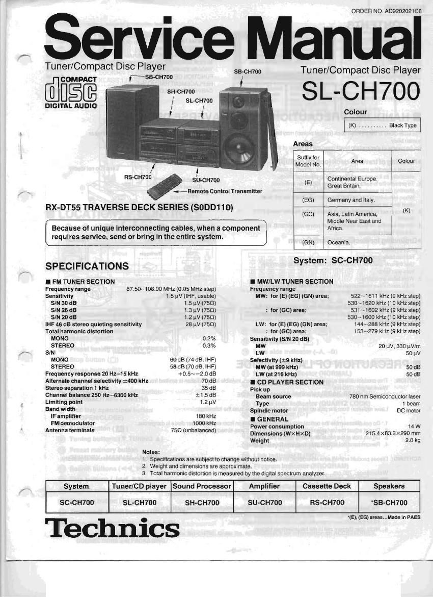
Technics SLCH 700 Service Manual

This is the 44 pages manual for Technics SLCH 700 Service Manual.
Read or download the pdf for free. If you want to contribute, please mail your pdfs to info@audioservicemanuals.com.

Page: 1 / 44
left right
Technics SLCH 700 Service Manual

Extracted text from Technics SLCH 700 Service Manual (Ocr-read)


Page 2

SL-CH700

I CONTENTS


Page
HANDLING PRECAUTIONS FOR TRAVERSE DECK ...... 2
PRECAUTION OF LASER DIODE ..
LOCATION OF CONTROLS

DISASSEMELV INSTRUCTIONS ..
MEASUREMENTS AND ADJUSTMENTS ..... ,

DESCRIPTION OF FL PANEL .. ... .... 15
SCHEMATIC DIAGRAM (Servo circuit) . .............. 16~i8
SCHEMATIC DIAGRAM

(Operation/Main/Loading Motor circuit) .............. 19~21

Page
SCHEMATIC DIAGRAM (Tuner clrcurt) ................ 22~24
PRINTED CIRCUIT BOARDS ........................ 25~27
WIRING CONNECTION DIAGRAM .
BLOCK DIAGRAM ............................ .

TROUBLESHOOTING GUIDE ...............
FUNCTION OF IC TERMINALS .
REPLACEMENT PARTS LIST .
CABINET PARTS LOCATION ......................... 45. 46

I HANDLING PRECAUTIONS FOR TRAVERSE DECK

The laser diode in the traverse deck (optical pickup) may break down due to potential difference caused by static electricity of clothes or

human body.

So, be caretui oi electrostatic breakdown during repair of the traverse deck (optical pickup).

OHandling of traverse deck (optical pickup)

1. Do not subject the traverse deck (optical pickup) to static
electricity as it is extremely sensitive to electrical shock.

2. To prevent the breakdown of the laser diode, an antistatic
shorting pin is inserted into the flexible board (FPC board).
When removing or connecting the short pin, tinish the job in as
short time as possible.

3. Take care not to apply excessive stress to the flexible board (FPC
board),

4. Do not turn the variable resistor (laser power adjustment). It has
already been adjusted.

CGrounding for electrostatic breakdown

prevention

1. Human bodygrounding
Use the anti-static wrist strap to discharge the static electricity
from your body.

2. Work table grounding
Put a conductive material (sheet) or steel sheet on the area where
the traverse deck (optical pickup) is placed. and ground the sheet.

Caution:

The static electricity oi your clothes will not be grounded through the

wrist strap. So, take care not to let your clothes touch the traverse

deck (optical pickup).

I PRECAUTION OF LASER DIODE

Optical pickup

Variable resistor/
(Do not turn)

FPC board
(Handle it carefully)

Be sure to short thisTpTJItion
(Use the shorting pin or clip.)

erst strap

Iron plate or some morals
to comma ulnarichy

CAUTION: This product utiiizes a laser diode with the unit turned on, invisible laser radiation is emitted from the pick up lens.

Wave length: 780 nm

Maximum output radiation power from pick up, 100 pWNDE

Laser radiation from the pick up lens is safety level, but be sure the followings:

Amp:-

. Do not disassemble the optical pick up unit, since radiation from exposed laser diode is dangerous.
Do not adjust the variable resistor on the pickup unit. It was already adjusted.

. Do not look at the focus lens using optical instruments.

. Recommend not to lock at pick up lens for a long time.

ACHTUNG: Dieses pradiikt enthalt eine laserdiode. im erngeschalteten zustend wird unstohtbare laserstrahiung von der lasereinheit abgestrahrt

WellenIAnge: 780 nm

Maximale strahlungsleistung der lasereinheit: 100 jiWNDE

Die strahlung an der lasereinheit ist ungeiahrlich, wenn tclgende punkte beachtet werden:

. Die Iasereinheit nicht zerlegen, da die strahiung an der freigelegten laserdiode getahrlich ist.
, Den werksseitigjustierten einstelireglerder lasereinreit nicht versteiien.

i
2
3. Nicht mit opiischen instrumenten in die tokussierlinse blicken.
4

. Nicht iiber langere zeit in die fokussierlinse blicken.

Page 13

FM OFFSET VOLTAGE AND MONO DISTORTION
ADJUSTMENT

1 Test equipment connection is shown in tigure1,5.

2 Set the unit to FM" mode.

a, Set the radio frequency display and signal generator to
100.10i0.001 MHz.

4. Adjust the core of T201 so that the voltage measured in Signal
mode is 0 mV (0:20 mV) in 300 mV range.

5. Adjust T202 so that the distortion factor of L-ch and R-ch is minimized.

6 Repeat steps 4 and 5.

Note: The adjusting screwdriver used should be made of resin.

FM SIGNAL GENERATOR CONDITION

Modulation ................ 100%
Modulation lrequency ........ 1 kHz
Output level ................ 66 GB
DC EVM
FM-SG

Chokecoil
5 3
.u : Put W 100 uH


FM ANT outnut
a a a

IRE] @I

cannon

FM MPX VCO ADJUSTMENT

1 Test equipment connection is shown in figure1,6.
Set the unit to stereo posrtion.

. Set the radio frequency display and signal generator to
63¢0.005 MHz.

. Adjust VR301 for 19 kH2130 Hz on lreduency counter reading.

(on)

J:

USING ALTERNATE SYSTEM

1. Receive the stereo broadcast.

2. Adjust VR301 until stereo indicator lights up. Fix the arm of
VR301 as shown in giture

FM SIGNAL GENERATOR CONDITION

Modulation 100%
Modulation irequency . _ .. 0 kHz
Output level ...... . 66:18

Fiequancy counter
FMSG

KPH I
in D
ISO 7, 0_
UI ' T
c, a ,7 PM W W» chassis
"Stereo" Stereo
OFF .

VR301
®-.,
@-® . . Stereo"OFFposition
®-® . "Stereo" ON position
(Indicator lighting)
© ........ Adjust pornt ot pilot Circuit

Fig.6

FM STEREO DISTORTION ADJUSTMENT

(EG only)

1. Test eqUipment connection is shown in figure.

2. Set the unit to FM" mode.

3. Set the radio frequency display and signal generator to
10010101101 MHz.

4. Adjust L1 so that the distortion factor of L-CH is minimized.

5. Make sure that the distortion factors of L-CH and R-CH are nearly
the same with each otherto minimum.

Notes:
1. The adjusting screwdriver used should be made of resrn.
2. L1 should be rotated no more 1/4 turn (90 dog.) on either side.

Outputrnnde ..L m R

FM SIGNAL GENERATOR CONDITION

Modulation .................. Stereo L" mode or R"
mode 45%, Pilot 10%

Modulation frequency . . 1 kHz (Pilot 19 kHz)

Output level ............ 66 dB

FMVSG Unll

[ERG

n-iu Out

Distortion analyser
FM ANT -- Output
.' a e. a

Adjust Within £90

to

L1

Fig. 7

Stereo modulator

Output (L ch)-= R335
Output (R 6h): H336

713-

SL-CH700

Page 18

0 | 1 1 1 2 I 1 3 I 1 4
Notes:
-8601 : Random switch
08602 : Tape side A/B selector switch
18603 : Fade swnch
'8604 : Normatfi ape length swttch
08605 : AI switch
08606 . Disc tray OPEN/CLOSE switch
08607 : Time mode selector swnch
08608 F skip switch
US$609 R, skip switch
ISGiO : Play switch
ISSii : Pause switch
-66l 2 : Stop switch
oSSl 3 : F. search switch
.3614 ; H. search switch
08615 ; Tuning UP SWitch
.8616 . Tuning DOWN swttch
.8617 : Preset UP SWllCh
98618 : Preset DOWN switch
v8619 : Band selector switch
08620 : Memory switch
IS701 : Rest switch
IS790 : Disc tray CLOSE detection swttch
08791 : Disc tray OPEN detection switch
Ilndicated voltage values are the standard values for the unit measured by the DC
electronic circuit tester (high-impedance) with the chassis taken as standard.
Therefore, there may exist some errors in the voltage values, depending on the
internal Impedance of the DC circuit tester.
: MUTING voltage
V» l' 'llr. (OperatiorVMain/Loading Motor circuit) Standard Play
filo l'ldlK (CD circuit) stop
Olmportant safety notice
Components identified by A mark have special characteristics important for safety.
When replacing any at these components, use only manufacturers speCIfied parts.
OThis schematic diagram may be modified at any time with the development of
3 W i new technology.
K -- . Positive voltage line
' - II - - Negative voltage line
' CD signal line
ira
> Caution!
r IC and LSI are sensitive to static electricity.
4* Secondary trouble can be prevented by taking care during repair.
an ICover the parts boxes made of plastics with aluminum coil.
ocx IGround the soldering iron.
ISL 0Put a conductive mat on the work table.
, > Elvflzcnsm) ODo not touchthelegs oilC or L8] withthe fingers directly,
m (wagezni

_15_