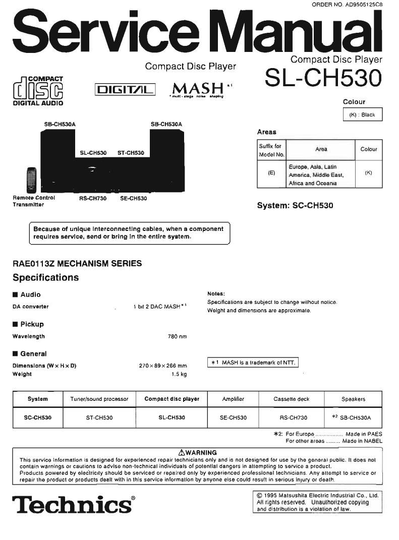
Technics SLCH 530 Service Manual

This is the 30 pages manual for Technics SLCH 530 Service Manual.
Read or download the pdf for free. If you want to contribute, please mail your pdfs to info@audioservicemanuals.com.

Page: 1 / 30
left right
Technics SLCH 530 Service Manual

Extracted text from Technics SLCH 530 Service Manual (Ocr-read)


Page 1

ORDER NO. A0950512509

Service Manual

Compact Disc Player

SL-CH53O

Compact Disc Player

COMPACT

MASH

'mnhmgn nan. mung

DIGITAL AUDIO

SECHSMA SB-CHSSOA

SL-C H530 ST-C H530

Remote Control
Transmitter

RMH730 SE-CH530

Because of unique Interconnectlng cables. when a component
requires service. send or bring In the entire system.

FIAE01132 MECHANISM SERIES
Specifications
Notes:

I Audio

DA converter 1 bII 2 DAC MASH"

Colour
(K) : Black
Areas
Suffix I Area Colour
Model No.

Europe. Asia. Latin
(E) America Middle East, (K)
Africa and Oceania

System: SC-CH530

Specifications are subject to change without notice.
Weight and dimensions are approxtmate.

l Pickup
Wavelength 780 nm
I General
Dimensions (w x Hx D) 270 x 89x 266 mm * MASH '5 *1 "edema ° NIT
Weight 1.5 kg
System Tuner/sound processor Compact disc player Amplifier Cassette deck Speakers
SC-CH530 ST-CHSGO SL-CH530 SEvCHSSO FIS-CH780 *2 SB-CHSSOA
*2: For Europem. Madein PAES
For other areas , Made in NABEL
AWARNING
This service Inlorrnatlon is designed Ior experienced repair technicians only and is not designed lot use by the general public, ll does not
contain warnings or cautions to advise non-technical individuals of polentlat dangers In attempling to service a product,
Products powered by electrictly should be serviced or repaired only by experienced prolesslonal technicians Any attempt to service or
repair the product or products dealt with in this service inlormation by anyone else could result in serious injury or death.

Technics®

© 1995 Matsushita Electric Industrial Co.. Ltd,
All rights reserved Unaulhonzed copying
and distribution is a VI°IEIBEBI law

Page 2

SL-CH530

l Contents

Handling Precautions tor Traverse Deck

Page

Printed Circuit Board Diagram 16~1a


Preoaution oi Laser Diode 2. 3 Wiring Connection Diagram. .. tB
Location ol Controls ..... .. Function oi IC Terminals 19~21
USW'IHQ IO Compact DISCS 3 Block DIagram.......... 22. 23
Operation Check and Troubleshooting Guide 24, 25

Main Component Replacement Procedures 4~7 Replacement Parts List. . 26~28
Automatic Adjustment Results Display Function Cabinet Parts Location ...... 29
Measurements and Adjustments Loading Unit Parts Location. 30


Schematic Diagram

NOTE:
Refer to the service manual for Model No. SE-CHSJO (ORDER No. A0950512602) tor information on "Accessories",
Stacking the Components", Connections" and Packaging".

CAUTION:

THIS PRODUCT UTILIZES A LASER.

USE OF CONTROLS OR ADJUSTMENTS OR PERFORMANCE OF PROCEDURES OTHER THAN THOSE
SPECIFIED HEREIN MAY RESULT IN HAZARDOUS RADIATION EXPOSURE.

l Handing Precautions for Traverse Deck

The laser diode in the traverse deck (optical pIckup) may break down due to potential diilarenco caused by static electricity at clothes or human body.
So. be carelui of electrostatic breakdown during repair at the traverse deck (optical pickup)

Variable reslslar

(Do not turn)

0 Handling of traverse deck (optical pickup) \

1. Do not subject the traverse deck (optical pickup) to static electricity as
it is extremely sensitive to electrical shock.

2. To prevent the breakdown oi the laser diode. an antistatic shonlng
pin is inserted into the flexible board (FFC board).
When removing or connecting the short pin. finish the job in as short
time as possible. FFC

3. Take care not to apply excessive stress to the flexible board (FFC
board).

4. Do not turn the variable resistor (laser power adjustment). it has al-
reaw been adjusted.

Optical pickup


Be sure to short this ponion -
(use the shorting pin or clip)

0 Grounding for electrostatic breakdown prevention 91'2 5'1!"192"
1. Human body grounding I g I I Q I
Use the anti-static wrist strap to discharge the start: electricity trom I w I I______I

your body.
2. Work table grounding
Put a conducive material (sheet) or steel sheet on the area where the
traverse deck (optical pickupl is placed. and ground the sheet.
Caution:
The static electricity at your clothes will not be grounded through the wnst
strap. So, take care not to let your clothes touch the traverse deck (optical
pickup).


Wrist strap
(Antietatic bracelet) /

tron plate or some metals to
conduct electricity

I Precaution of Laser Diode

CAUTION: This product utilizes a laser diode with the unit turned "on". invisible laser radiation is omitted lrom the pick up lens.
Wave length: 780 nm
Maximum output radiation power lrarn pick up: too uWNDE
Laser radiation lram the Pick up unit is salary level. but be sure the lollowlngs:
i. Do not disassemble the pick up unit. since radiation lrom exposed laser diode is dangerous.
2. Do not adtust the variable resistor on the pick up unit. It was already adjusted
3. Do not luck at the focus lens using optical instruments.
4. Recommend not to lock at pick up lens tor a long time.
ACHTUNG: Dieses orodukt enthalt eine laserdlode. irn elngeschalteien zustand wtrd unsiohtoare Iaserstrahtung von tier Iasereinhert

adgestrahit.
Wellenlange: 780 nm
Maximale stmhlungsteistung der laserlnheli; 100 uWNDE

Die strahlung an der Iasorelnheit isl ungolahrilch. wenn lolgende punkte beachtet werden:

I. Die lasereinheil nicht zerlegen. da die strahlung an der lreigelegten Iaserdlode geiéhrilch ist.
2. Don werksseitig lustienen einstellregier der lasereinreit nicht verstellen.

3. Nicht mil optischen instrumenten in die lokussierlinse blicken.

4. Nicht Ubel tangere zeit in die tokussiarltnse blicken.

Page 20

O |C701 (ANBBOZSCE1V)

0 |C7D2 (MN66271 RA)

Pln Terminal P
No. Name V0 F"°"° NI: TeeranTl l/O Function
I PDAD l PD A channel signal input erh delay I BCLK 0 Bit clock Dulpul in! serial data Inc used. open)
2 FDA I PD A channel signal Input without Itolay 2 LFtCK - L/R identification signal output (no used open)
_ l -
3 LPD | Laser PD connection 3 SFlDATA Serial data output (no usedr open)
4 DVDDI - Power supp in ut (lor digital Circuitl
4 LD 0 Power supply tor LD driving W p
5 DVssI - GND (lur digital circuit)
5 AMPI l RFamplilier Input
6 TX 0 Digital audio interlace signal outpul
5 VCC l POWBF SUDNY connection Microprocessor command clock si nal Input
7 MCLK (Latches data at first transition) 9
, j r
7 AMPO 0 RF amplifier output (no used, we") B MDATA l Microprocessor command data Signal input
a CAGC I AGO loop 6' comemmn 9 MLD l MIcroprocessor command load Signal input
Sense Sl nal output
9 AF": 0 HF "Gc WW m SENSE o , ($2). F SL MAGEND, NAJEND, POSAD
lO CENV I Capacitor connection lor HF detection
I I IFLOC:K 0 Focus servo loedlng signal output (L: Feed)
1 t CEA l Capacitor connection tor HPF ampliiier 2 /TLOCK O FfifgggdfiEND feeding signal output
12 GND - Ground connection Sub-code block clock Signal output g
3 BLKCK O (tBLKCK = 75 Hz durrng normal playbacklii
ra LDON I ON/OFF input at LD AFC ("H': an L om 14 509K | 3:32? °'°°k 5'9 "'9 '° mm 0
t4 TES | Tracking error shunt Signal input ll-l": shunt) l5 SUBO 0 I Subecodo 0 code output
l5 PLAY I Play signal lnpul ("l-l": PLAY) '6 DMUTE I Milling mm ("H Mulel
l7 STAT 0 Status sr nal out ul
16 WVEL | WVEL control (CHC. C E, CL 5. TTSTVP FCLV. SOCK)
IB FIST | Reset n uI
17 BD0 0 BBC output / ' "
Mggtvidogrclock Signal of crystal oscrllatlng at
l8 IFIFDET 0 NRFDET output (ISMClZ- B 4572 MHzl
- I9 SMCK - , . ' , ,
iM-diwded clock signal 0! crystal oscfllating at
l9 CROSS 0 CROSS output MSEL ; "Lu
T [lSMCK : 4.2336 MHz) (no used. opent _
20 DFTFt O OFI'R output , 1/1 92-6 'ded clock Signal ol crystal oscrllatrng
2° WC - liPMCK = 33.2 kHz) lno used 993
2 VDET O VDET output 21 TRV O Traverse lorced teed output
22 ENV O ENV Wm" 22 W0 0 Traverse drive outpul
23 TEBPF | Vibration detection input 23 PC 0 Spindle motor ON signal output (1.: ON)
Spindle motor drive 5: rial output [forced model
24 TE 0 Tracking error output 2" ECM ipulpul) g
Spindle motor drive Signal output (servo error
25 FE 0 Focus error output 25 ECS ( 0 Signal output)
7 26 KICK o K'ck tool I
26 PTO O Polentioamplifier output lno used open] I p S D p _
Polenlloamplifier anElSlOn input 27 TRD 0 Tracking 5" output
27 PTI I r r_
lno used. open]
28 FOD 0 Focus drive output
28 TBAL | Tracking balance input D/A (drive) 0!le (TVD ECS. TRD. FOD.
29 VHEF FElAL. TEAL] relerence voltage input
FBAL | F0 b l l t
29 cus a once Du 30 FBAL 0 Focus balance adjustment output
30 VFlEF O VFlEF output 3l TEAL 0 Tracking balance adjustment output
3| PDB I PD B channel Signal input without delay 32 FE | Focus error signal inpul (analog inpul)
32 PDBD | PD B channel Signal input with delay 83 TE | Tracking error Signal Input (analog input)
34 RFENV | HP envelope Signal input
35 VDET | Wbralion detection Signal input (HL detection)