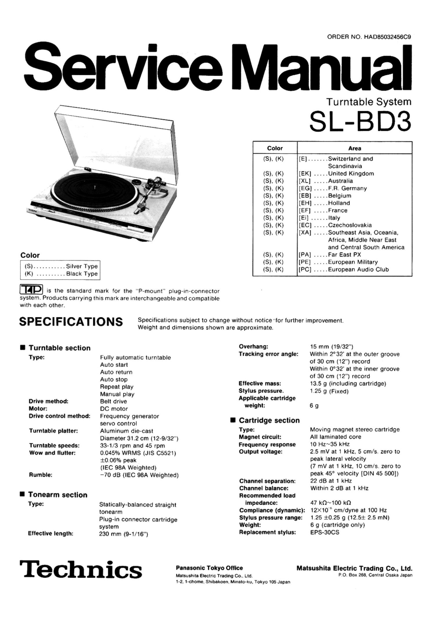
Technics SLBD 3 Service Manual

This is the 16 pages manual for Technics SLBD 3 Service Manual.
Read or download the pdf for free. If you want to contribute, please mail your pdfs to info@audioservicemanuals.com.

Page: 1 / 16
left right
Technics SLBD 3 Service Manual

Extracted text from Technics SLBD 3 Service Manual (Ocr-read)


Page 1

ORDER NO. HADB503245609

Service Manual

Turntable System

SL-BD3

Color Area
(3). (K) [E] ....... Switzerland and
Scandinavia
(S). (K) [EK] ..... United Kingdom
(S). (K) [XL] ..... Australia
(8). (K) [EG] .....F_R. Germany

(8). (K) [EB] ..... Belgium

(8). (K) [EH] ..... Holland

(8). (K) [EF] ..... France

(3). (K) [Ei] ...... Italy

(8). (K) [EC] ..... Czechoslovakia

(S). (K) [XA] ..... Southeast Asia. Oceania.

Africa, Middle Near East
and Central South America

Color (8). (K) [PA] ..... Far East PX
_ (S). (K) [PE] ..... European Military
(8) ........... Silver Type .
(K) _________ Black Type (S). (K) [PC] ..... European Audio Club

,__
up is the standard mark for the "P-mount" plug-in-connector
system. Products carrying this mark are interchangeable and compatible
With each other.

SPECIFICATIONS

Specifications subject to change without notice 'for further improvement.
Weight and dimensions shown are approximate.

I Turntable section
Type:

Drive method:

Motor:

Drive control method:
Turntable platter:
Turntable speeds:

Wow and flutter:

Rumble:

I Tonearm section
Type:

Eitective length:

Fully automatic turntable
Auto start

Auto return

Auto stop

Repeat play

Manual play

Belt drive

DC motor

Frequency generator

servo control

Aluminum die-cast
Diameter 31.2 cm (12-9/32")
33-1/3 rpm and 45 rpm
0.045% WRMS (JlS 05521)
i0.06°/o peak

(IEC 98A Weighted)

-70 dB (IEC 98A Weighted)

Statically-balanced straight
tonearm

Plug-in connector cartridge
system

230 mm (9-1/16")

Overhang:
Tracking error angle:

Eilective mass:

Stylus pressure.

Applicable cartridge
weight:

I Cartridge section

Type:

Magnet circuit:
Frequency response
Output voltage:

Channel separation:

Channel balance:

Recommended load
impedance:

Compliance (dynamic):

Stylus pressure range:
Weight:
Replacement stylus:

15 mm (19/32")

Within 2°32' at the outer groove
of 30 cm (12") record

Within 0°32' at the inner groove
of 30 cm (12") record

13.5 9 (including cartridge)
1.25 9 (Fixed)

69

Moving magnet stereo cartridge
All laminated core

10 Hz~35 kHz

2.5 mV at 1 kHz. 5 cm/s. zero to
peak lateral velocity

(7 mV at 1 kHz. 10 cm/s. zero to
peak 45° velocity [DIN 45 500])
22 dB at 1 kHz

Within 2 dB at 1 kHz

47 kn~100 k0

12X10 " cm/dyne at 100 Hz
1.25 $0.25 9 (12.521: 2.5 mN)
6 g (cartridge only)
EPS-3OCS

Panasonic Tokyo Otiice

Matsushita Electric Trading Co.. Ltd.
1-2. 1-chome. Shibekoen, Minato-ku. Tokyo 105 Japan

Matsushita Electric Trading Co., Ltd.
Po. Box 288. Central Osaka Japan

Technics

Page 2

I General Dimensions: 43 x 10 x 37.5 cm

and Australia: 240V. AC 50 Hz Maximum height when 09
For continental (dust cover) is open.

43 x 37 x 41 cm
Europe: 220V. AC 50 Hz .. .. ..
For others: ~110~127/220~24ov, 645/16 X 14'9/16 X 161/8 )

50/60 Hz "99"" 8.8 kg (8.4 lb.)
Power consumption: 3 w
I C0 NTENTS

Page
SAFETY PRECAUTION ..................................................................... 2
LOCATION OF CONTROLS ................................................................ 3
DISASSEMBLY INSTRUCTIONS ......................................................... 3 ~ 5
MEASUREMENTS AND ADJUSTMENTS .................................................. 6. 7
TROUBLESHOOTING .................................................................... 7, 8
SCHEMATIC DIAGRAM ................................................................. 9, 10
BLOCK DIAGRAM ................................................................... . ..... 9
CIRCUIT BOARD AND WIRING CONNECTION DIAGRAM .................................. 11
OPERATIONAL DESCRIPTION OF MECHANISM ...................................... 11 ~ 13
EXPLODED VIEW .................................................................... 14 ~ 16
REPLACEMENT PARTS LIST ........................................................... 17, 18

I SAFETY PRECAUTION

Before servicing, unplug the power cord to prevent an electric shock.

When replacing parts, use only manufacturer's recommended components for safety.

Check the condition of the power cord. Replace if wear or damage is evident.

After servicing, be sure to restore the lead dress, insulation barriers, insulation papers, shields, etc.

Before returning the serviced equipment to the customer, be sure to make the following insulation resistance test to
prevent the customer from being exposed to a shock hazard.

QPWN.

. INSULATION RESISTANCE TEST

1. Unplug the power cord and short the two prongs of the plug with a jumper wire.

2. Turn on the power switch.

3. Measure the resistance value with ohmmeter between the iumpered AC plug and each exposed metal cabinet part, such as
screwheeds antenna, control shafts. handle brackets, etc. Equipment with antenna terminals should read between 3M9
and 5.2MSI to all exposed parts. (Fig. A) Equipment without antenna terminals should read approximately infinity to
all exposed parts. (Fig. B)

Note: Some exposed parts may be isolated from the chassis by design. These will read infinity.

Antenna
terminal

Exposed
metal
part

Resistance = 3MQ-52MQ Resistance = Approx 00

4. If the measurement is outside the specified limits, there is a possibility of a shock hazard. The equipment should be
repaired and rechecked before it is returned to the customer.

-2-