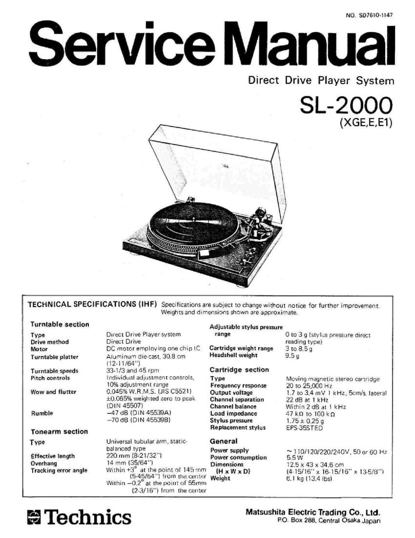
Technics SL 2000 Service Manual

This is the 12 pages manual for Technics SL 2000 Service Manual.
Read or download the pdf for free. If you want to contribute, please mail your pdfs to info@audioservicemanuals.com.

Page: 1 / 12
left right
Technics SL 2000 Service Manual

Extracted text from Technics SL 2000 Service Manual (Ocr-read)


Page 1

NO. 3976104?

Service Manual

Direct

Drive Player System

SL- 2000

(XGE, E, E1)

3 TECHNICAL SPECIFICATIONS (IHF) Spectlications are sublect to change without notice for further impmvement
Weights and dlmEllSIODS Shown are approximate.

Turntable section

Type
Drive method
Motor

Turntable platter

Turntable speeds
Pitch non trols

Wow and flutter

Rumble

Tonearm section
Type
Effemiue length

Overhang
Tracking error angle

Direct Drive Player system
Direct Drive

DC motor employing one chip IC
Aluminum diecast 30,8 cm
[l2] 1/54"]

33-1/3 and 45 rpm

individual adjustment controls,
10% adiusmenr range

004.6% W.Fl .M_St lJlS C5521)
i0.065% weighted zero to peak
(DIN 45507l

-47 dB (DIN 45539A)

470 dB (DIN 455398)

Universal tubular army static

balanced type

220 mm (8v2l/32)

14 mm (351540

Within +3 at the DOIHI or 1.15 mm
l5~45l64l from the center

Wllhin -0.2° at the palm of 55mm
(QB/16') lmm [he tamer

Technics

Adjustable stylus pressure

range

Cartridge weight range

Headshell weight

Cartridge section

Type

Frequency response
Output voltage
Channel separation
Channel balance
Load impedance
Stylus pressure
Replacement stylus

General
Power supply
Power consumption
Dimensions

(H x W x DI
Weight

0 to 3 g [stylus pressme direct
reading tytpel

3 m 8.5 9

95 9

Moving magnetic stereo cartridge
20 to 25,000 Hz

1.7 to 3,4 mV l kHz, Ecru/s. lateral
22 dB at 1 kHz

Within 2:18 31 l kHz

47 km to 100 km

1.75 i: 0.25 g

EPS-3SSTED

~110/l20/220/240V. 50 or 60 Hz
55 W

12.5 x 43 x 34,613
(445/16" X 16-15/16" x 8-5/8")
6.] kg 113.4 lbsl

Matsushita Electric Trading 00.. Ltd.

PO Box 288. Central Osaka Japan

Page 2

I PARTS IDENTIFICATION

Phono terminals

Ground wire


AC powet plug

45 rpm adaptor

Shell stand AC power cord

Balance weight

Stylus plessure ring

Anti-skating conirol knob

Arrn res!


Cuelng lever

Tubular arm
cn control knobs
Locking mlE

Power Switchlspead seleclor

I 'I' 11% I

Play case I Headshelllcartridge
Tumlable planar Strobe dok indication

Tumble mat Strobe dots

M 010! shafl (Center spindle) Strobe illuminator/pilot lamp

Fig.1
l ASSEMBLY AND SET-UP

Horizontally balanced stale 1.Adiustmenls of the horizontal "0" balance and the

svylus pressure

Balanmwllghl 3'40.- aerslmg We lmrlmntal "0" uemnue, check fol
"5er I" the fl9ll0wmg «terns

[ubglar um

C"9'°"°' ll Ensure that the enemy IeVLll as .n :le: Iowa-ad

position d5 Shawn In Fig. 2.

22! Ensuru "H! W? lllfl-Skétlllg klufi: 1'« 4L 0 DOS!
ll'Jll [Sn-eFIq ll

3F Mala: .urmm rlml llm nuwer Wm r .lgpo-nrl Wm
lur ls m 'OF F" pnjmml. ISUI: l ll; ll

Mmml lll»: balm-J: WEIHIII. (m lint: ltmuaml mar shall
(5w: Fun. 2)