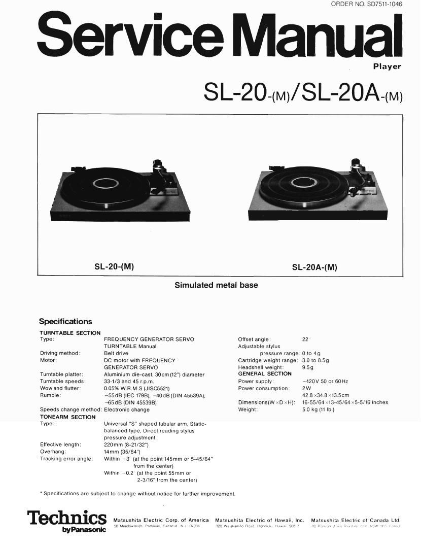
Technics SL 20 Service Manual

This is the 12 pages manual for Technics SL 20 Service Manual.
Read or download the pdf for free. If you want to contribute, please mail your pdfs to info@audioservicemanuals.com.

Page: 1 / 12
left right
Technics SL 20 Service Manual

Extracted text from Technics SL 20 Service Manual (Ocr-read)


Page 1

ORDER NO SD7511-1046

ervice Manual

SL'20-(M)/

Player

8 L'20A-(M)

SL-20-(M) SL-20A-(M)

Simulated metal base

Specifications
TURNTABLE SECTION
Type: FREQUENCY GENERATOR SERVO Oilset angle
TURNTABLE Manual Adjustable stylus
Driving method: Belt drive pressure range:
Motor: DC motor with FREQUENCY Cartridge weight range
GENERATOR SERVO Headsheli weight:
Turntable platter: Aluminium die-cast, 30cm (12") diameter GENERAL SECT'ON
Turntable speeds: 33-1/3 and 45 rpm. Power supply:
Wow and llutter: 0.05% W.R,M.S (JISC5521) Power consumption:
Rumble: -55dB (lEC l798), 40118 (DIN 45539A),
$5dB (DIN 45539B) Dimensions(W x D xH):
Speeds change method: Electronic change Weight.
TONEARM SECTION
Type: Universal "8" shaped tubular arm, Static-
balanced lype, Direct reading stylus
pressure adjustment.
Effective length. 220mm (8~21/32")
Overhang: 14mm (35/64")

Tracking error angle: Within +3" (at the point 145mm or 5-45/64"
lrom the center)
Within 70.2 (at the point 55mm or
23/16" from the center)

Specifications are subject to change without notice for lurther improvement.

0
Technlcs Matsushita Electric Corp. oi America Matsushita Electric of Hawa

| P . 50 Mcaaowano, Pa'kwav 59:05.15 NJ (Mom 7,20 Wmammo Mm Horvwmu mun

22

Oto 4g
30to 859
9.59

~120V 50 or 60H:

2W

42.8 x345 x13 5cm

16-55/64 V13~45/64><5-5/16 inches
5.0 kg m In.)

Matsushita Electric at Canada Ltd

H: «m- -vv 1W, :mm. mm vw vw r, i m

Page 2

OPERATING PRINCIPLES OF FREQUENCY GENERATOR
SERVO MOTOR

' A Frequency Generator is mechanically coupled to the motor shaft its output is in direct protection
to motor speed.

The signal produced by the Frequency Generator is amplified and converted to a square wave by the
pulse shaper circuit.

' The square wave is then converted into a trigger pulse.

' A square wave of fixed amplitude (ES) and width (TS) is generated using the trigger pulse to de-
termine the square wave frequency. Therefore. this square wave has a frequency (T) which is directly
related to the speed of the motor.

' An integrated circuit converts this square wave into a ramp wave which is used as the motor control
voltage. (Ei) If the motor speed is too fast. the output of the Frequency Generator will be higher than
normal causing a decrease in the period (T) of the square wave signal. This results in an increase in
the motor control voltage (Ei). Thus the motor control voltage (Ei) is also in direct proportion to the
motor speed.

' In the voltage comparator stage. the motor control voltage (Ei) is compared with the reference
control voltage Es/n which is supplied from the reference voltage supply and divider circuits.

' The output of the comparator (Ec) is the actual motor control voltage which will adjust the motor
speed based on the signal supplied by the Frequency Generator.

' A phase compensator is used to teed back the AC component of the motor drive voltage to the
voltage comparator, to improve speed stability,

SPEED SELECTION
The two playing speeds are selected by varying

. . . L h t
the square wave pulse wrdth (Ts) With two variable oad c arac enstics

resistors. Stylus pressure (9)
o 2 4 e a
LOAD CHARACTERISTICS (Fig. 15) I l
This chart indicates the fluctuation of the rotational E *2 i ' ' jm * ~ * fl» 4-' ~
'0 ' l
speed of the turntable in relation to the Stylus pres g 0.4 . , 7 -i 7 1,7
sure values. 2 0 6 W _. 7 ,7 7 7
' This unit employs a DC motor with an FREQUENCY 5; I
GENERATOR SERVO circuit so that the load charac I 0- 177717 f 7. 777*?
teristics are extremely good. 1.0 l
PTA
T T T ITJ T 5'H Phase com-
I_I I I LESI M pensat or
circuit
P | T C st | a. v I DC 5; Mmor Em
Amptlllor stiaspeer -> pIIIgsgeer llfrIo guns. I») aggred czéapiza. 3) amplifier driving M
circuit circuit generator I tor circuit
/ F G (Frequency Generator) /
/ Es/n /
/ Refinance 33 5 /
/ Eggzg E5 Divider /
/ circuit 1/n /
L. ____________________________________ _/

CZI SL-20-(M)/SL-20A-(M)

Page 4

SCHEMATIG DIAGRAM

.- - -.
403
I : ca . l
553: 3:047 0~210 D.D|)I' TOBY):
w -R '
W 8722 0' .
, cu r __________________ 0 12 __9.P°_'PE3§.~_
_| m _2 It: 00%}: 5 s 7 B
l
Pow?! W236
'T «a *Rfi
{5:315:17}? m 4 393
an 3 3?,
4

______________J

t a 1 I .1
_____ _____________________ o-~
882»? 5 chaos»
" (2 94
on Ail
|
4 mgix WINK
R36 47K we '- __________________________
' \N In :
I
|_ _________________ J

CIRCUIT BOARD

EPA 11-.

SIRBIO

E4] SL-20-(M)/SL-20A-(M)