Technics SL 1900 Owners Manual

This is the 19 pages manual for Technics SL 1900 Owners Manual.
Read or download the pdf for free. If you want to contribute, please mail your pdfs to info@audioservicemanuals.com.

Page: 1 / 19
left right
Technics SL 1900 Owners Manual

Extracted text from Technics SL 1900 Owners Manual (Ocr-read)


Page 1

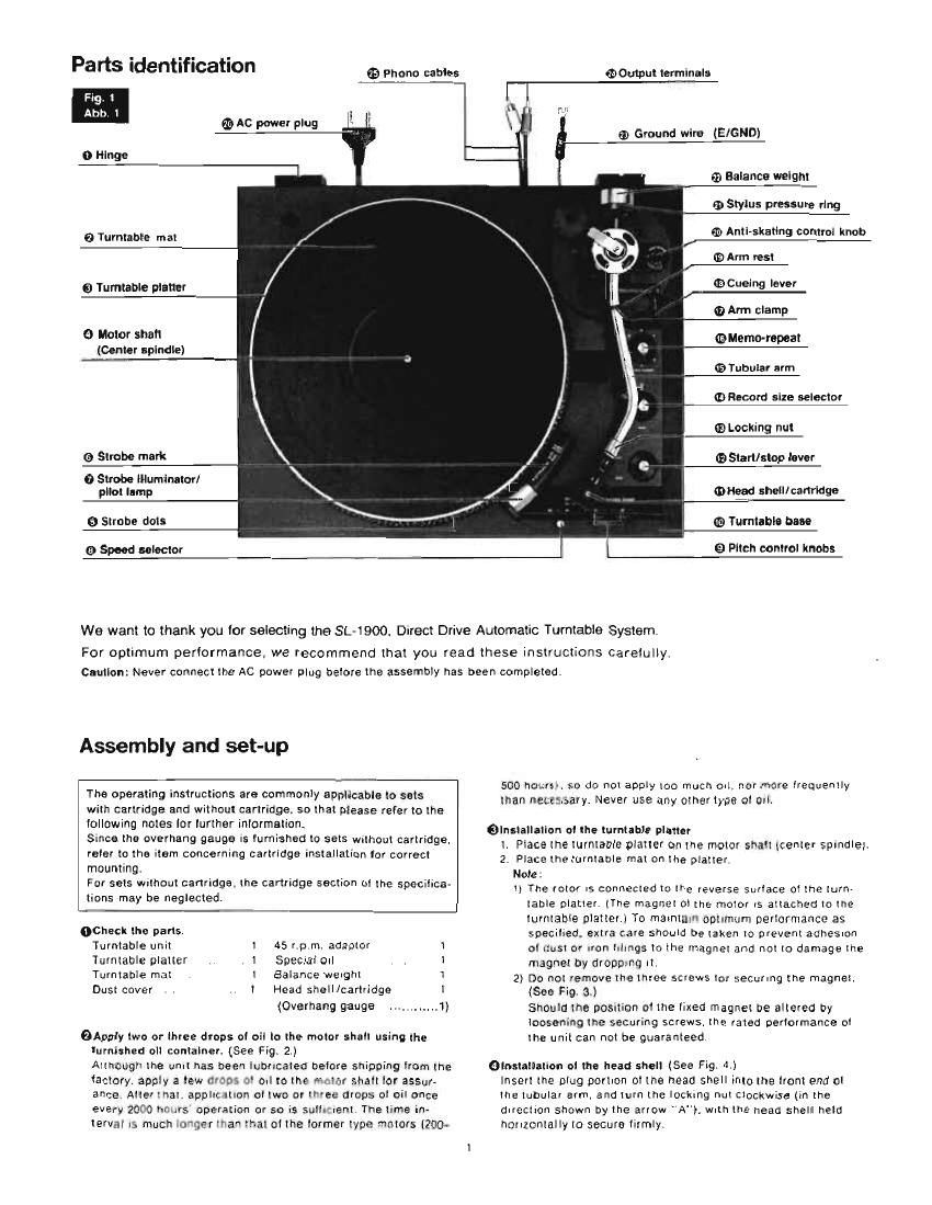
Parts identification

. Qihono cables

@Output terminals

F
Ab

Q AC power plug " l

0 Hinge

0 Turntable mat

0 Turntable platter

0 Motor shalt
£Center spindle)

G Strobe mark

0 Strobe lllumlnator/
plrot lamp

0 Strobe dots

0 Speed selector

® Ground wire (EIGND)

r1) Balance welght
m Stylus pressure ring
(a. Anti-skating control ltnob

® Arm rest

.7 ® Cueing lever
0 Arm clamp
@Memo-repeat
Q Tubular arm
mflecord slze selector

/ ® Locking nut

0 Start/stop lever
0"?in shell/cartridge

rm Tumiabla base

i El Pitch control knobs

We want to thank you for selecting the SL-1900. Direct Drive Automatic Turntable System.

For optimum performance. we recommend that you read these instructions carelully.
Caution: Never connect the AC power plug belore the assembly has been completed.

Assembly and set-up

The operating instructions are commonly applicable to sets
with cartridge and without cartridge, so that please refer to the
lollowing notes [or lurther inlormelion.

Since the overhang gauge is furnished to sets wrlhoul cartridge.
refer to the item concerning cartridge installation tor correct
mounting.

For sets Without cartridge. the cartridge section ol the spacilica-
lions may be neglected.

ochaclt the pans.

Turntable unit 45 rpm. adapter

1
Turntable platter . . l Specual Oll
Turntable mail I Balance weight
Dust cover l Head shell/cartridge

_t_...i_.-

(Overhang gauge

OApply two or three drops ol oil to the motor shalt using the
iurnished oll conlalner. (See Fig. 2.)
Althougl the unit has been iuoricaleo belore shipping tram tne
tactory. apply a tow crap; 0' Oil to the mctcr shalt lcr assur-
ance Alter ' rial appltt IlliDll 0! two or "61; drops ol oil once
every 20ft) hr: urs operation or so is suit-went The time in-
terval is much ram than that ol the lormer type ~rotors [2700»

500 hcm so do not apply too much out, nor more lrequently
than new nary. Never use any otherlyps at all.

elnstallatlon at the turntable platter
1. Place the turntable platter on the motor shalt \center spindle}.
2. Place the turntable mat on the platter.

Note:

l) The rotor IS connected to the reverse surlace ol the turn
table platter. (The magnet ol the motor is attached to the
turntable platterl To maintain optimum perlormance as
specified. extra care should be taken to prevent adhesion
oi dust or iron hlmgs to the magnet and not to damage the
nugnet by dropnirq it.

2) Do not remove the three screws tor seCuring the magnet.
(See Fig. 8.)

Should the position ol the lixed magnet be altered by
loosening the securing screws. the rated perlormance or
the unit can not be guaranteed

Olnstatlation ol the head shell (See Fig. 4.)
Insert the plug portion at the head shell into the lront end at
the tubular arm. and turn the locking nut clockwise (in the
direction shown by the arrow ). With the head shell held
horizontally to secure lirmly.

Page 2

eAdjuslments ol the horizontal 0" balance and the stylus pressure

1. Insert the balance weight unto the rear shall at the tonearm.
(See Figs. 5.)

2. Flemove the stylus cover. it your cartridge has one.

3. Release the arm clamp (Fig. 6) and lilt the tonearm lrom
the arm rest to lree the tonearm.
Note:
It the tonearm is urged to return to the arm rest when the
loneerm is held in a lree state in Fig. 7. rotate the turntable
platter clockwise about 10 times. This is necessary because
in rare cases the automatic mechanism may have engaged
the tonearm gear or moved out of its normal position during
transportation.

5'

turn the entire balance weight clockwise (indicated by the
arrow "A') or countrerclockwise (indicated by the arrow "8")
until the lonearm is approxrmately balanced horizontally.
(See Figs. 7 and a.)

5 Alter the lonearrn is horizontally balanced. temporarily lix the
tonearm by the arm clamp, (See Fig. 9.)

Hold the balance weight stationary wrth lingers as shown in
Fig. 9 and rotate only the stylus pressure ring to bring the
numeral "0" ol the ring into alignment thh the center line
on the tonearm rear shall. (the aaluslmenl ol the horizontal
balance is now completed.)

Note:

1) During the adtuslment ol the horizontal balance. be sure
that the stylus lip ol the cartridge does not contact the
turntable met or turntable base.

Zl Ensure that the anti-skating knob rs at "'-'0 position.
(See Fig. 9.)

There are cases where the tonearm may sway or llow
slightly at the positron ol "0" due to the highly sensnive


Plug
Stacker
Broche

Plug
Stlckltantaltt
Clavlia

Locklng nut
Klemmrlng
Bague de blocage
Alslultmoer
Litsmutter

Tuema de fllaclon


: . dds d'equlllhrage

cht
rlngsviltl

rapuo depalanco

v


rotational part ol the tonearm, out this side lorce lS trivial
and nrasents no inconvenience.

3) Ensure that the cueing lever is in the lowered position as
shown in Fig, 6.

4) Make certain that the speed selector is in the "." position.
the balance adtustment is easrly made as the turntable
platter remains stationary.

6 Alter adjusting the horizontal balance. turn the balance weight
clockwrse in the direction 01 the arrow and align the correct
stylus pressurettJSg). (See Fig. 10.)

Note:

I) As the stylus pressure ring rotates together with the ba-
lance weighl, proper stylus pressure can be selected by
directly reading the graduated ring.

In cases where the recording level at a record is ex»

tremely high or the unit is used in a room haying low

temperature or records are played in places where

Vibrations are liable to be transmitted to the turntable

system. distortion" ol sound or "skipping" ol stylus

may take place In such cases. set to "2 g lor optimum
perlormance.

2

@Antl-lltatlng lorca central
Set the anti-skating control knob to the same value as that set
lor stylus pressure. [See Fig 11.)

Olnsull-tlon ol the dim cover (See Fig. 12.)
Place the dust cover into position lrom directly above, holding it
at both sides. For detaching the dust cover, be certain lirst to
raise it as illustrated belore removal.