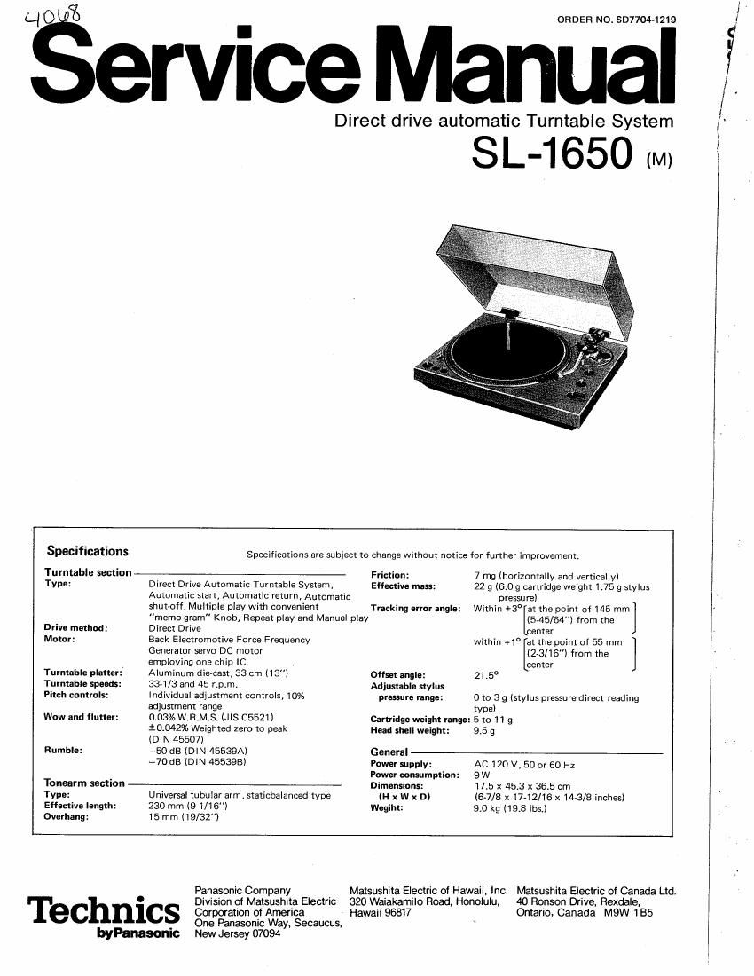
Technics SL 1650 Service Manual

This is the 12 pages manual for Technics SL 1650 Service Manual.
Read or download the pdf for free. If you want to contribute, please mail your pdfs to info@audioservicemanuals.com.

Page: 1 / 12
left right
Technics SL 1650 Service Manual

Extracted text from Technics SL 1650 Service Manual (Ocr-read)


Page 1

fiervice

ORDER NO. SD7704- 1219

Manual

Direct drive automatic Turntable System

SL-165O (M)

Specifications

Turntable section
Type:

Drive method:
Motor:

Turntable platter:
Turntable speeds:
Pitch controls:

Wow and flutter:
Rumble:

Tonearrn section
Type:

Effective length:
Overhang:

Specifications are subject to change without notice for further improvement.

Direct Drive Automatic Turntable System,
Automatic start, Automatic return, Automatic
shutoff, Multiple play with convenient

"memogram" Knob, Flepeat play and Manual play

Direct Drive

Back Electromotive Force Frequency
Generator servo DC motor
employing one chip IC

Aluminum die~cast, 33 cm (13)
33-1/3 and 45 rpm.

Individual adjustment controls, 10%
adjustment range

0.03% W.R.M.S. (.llS C5521)
i0042% Weighted zero to peak
(DIN 45507)

~50 dB (DIN 45539A)

--7DdB (DlN 455393)

Universal tubular arm, staticbalanced type
230 mm (9-1/16)
15 mm (19/32)

Friction :
Effective mass:

Tracking error angle:

Offset angle:
Adjustable stylus
pressure range:

7 mg (horizontally and vertically)
22 9 (5.0 g cartridge weight 175 9 stylus
pressure)

Within +3 at the point of145 mm
[(645/64") from the
center

within +1° at the point of 55 mm
(ZS/16") from the
center

215°

0 to 3 g (stylus pressure direct reading
type)

Cartridge weight range: 5 to 11 9
Head shell weight: 95 9
General
Power supply: AC 120 V, 50 or 60 Hz
Power consumption: 9 W
Dimensions: 17.5 X 45.3 x 36.5 cm
(H x W x D) (SJ/8 x17-12/16 x 1443/8 inches)
Wegiht: 9.0 kg (193 ibs,)

Technics

byPanasonic

Panasonic Company

Corporation of America
One Panasonic Way, Secaucus,
New Jersey 07094

Division of Matsushita Electric 320 Waiakamilo Road, Honolulu.
Hawaii 96817

Matsushita Electric of Hawaii, inc. Matsushita Electric of Canada Ltd

40 Ronson Drive, Rexdale,
Ontario, Canada M9W 185

/l.

I
i
i
l

Page 2

\

I Parts identification

AC power plug

Hinge

Turntable mat


Turntable platter

Motorshaft
(Single play spindle)

Strobe dots

Strobe illuminatorl
pilot lamp

Speed selector 0 ?


Output terminals

é Ground wire


Balance weight

Stylus pressure ring

Anti-skating
control knob

Cueing lever

Arm rest
AW

Arm clamp
Record size selector

Tubular arm
Locking nut

Start/stop lever
Head shell

Pitch control knobs

I Assembly and set-up

Apply two or three drops of oil to the motor shah
using the furnished oil container. (See F ig. 2)

Although the unit has been lubricated before shipping
from the factory, apply a few drops of oil to the
motor shaft for assurance After that, application of
two or three drops of oil once every 2000 hours

operation or so is sufficient.

The time interval is

much longer than that of the former type motors
i200 - 500 hours). so do not apply too much oil, nor
more frequently than necessary. Never use any other
type of oil.

@PFDN.

0)

Remove headshell and balance weight.

Clamp tone arm to the arm rest.

Remove turntable platter.

Close dust cover.

Turn unit upside down taking special care not to damage
or scratch the dust cover.

. Remove the 4 legs and the 6 screws from bottom cabinet

(main base) (Fig. 1).

SL-1650

Turntable base

, Holding the player firmly with both hands, to prevent

separation of upper section (turntable base) from lower
section (main base), turn it carefully upwards.

Remove the 4 screws from the protective top panel (Fig.
2).

. Unplug the 3 plug-in connectors (main base).
. To remove the turntable base from the main base bot-

tom section, turn cueing lever upward (cueing position)
and move tone arm towards center of spindle. Top sec-
tion can be lifted up easily. (Fig. 3).

Note:

The turntable horizontaliy to the panel face is
already adjusted before shipment.

If deviated, correct it by means of the adjust
screws using a 5mm box spanner.

Mun. audio
insulallonflpnng 1
EGJUSIMOM

Fig. 1


.7 Prnlecinm Dlnet
, Turnlal'tle has:

~90} "

Lever, euelnq

Connector!

Fig. 3

Page 5

I Explanation of each part

I. B.F.G. METHOD (BACK ELECTROMOTIVE
FORCE FREQUENCY GENERATOR)

Making use of the back electromotive force that is
generated in the drive coil winding of the motor as a
frequency generator, the frequency of the frequency
generator is converted to the number of revolutions for
the turntable.

After shaping the wave form of this back electromotive
force, it is composed logically, and a frequency is
generated that is proportional to the number of revolu-
tions. This is the use of the B.F.G. Making use of the
drive coil winding, frequency generator coil windings
and magnets are not necesary, yielding a motor struc~
ture that is very compact.

2. FREQUENCY-VOLTAGE CONVERSION CIRCUIT

Being composed of a trapezoldal wave generating circuit,
a pulse generating circuit and a sampling integration cir-
cuit, the B.F.G. output frequency is converted to a vol-
tage, and control output voltage is generated in order to
maintain the rotational speed of the turntable at a cons-
tant level.

I Block diagram

3. OPERATION CONTROL CIRCUIT

The operation control circuit functions as a control out-
put voltage control keeping the rotational speed of the
turntable constant with regard to the start of turntable
operation and the operation of the mechanism. With
this circuit, transient response characteristics and start-
ing characteristics are very good.

4. OPERATIONAL AMPLIFIER (OP AMP) ACTIVE
FILTER

Because of using an operational amplifier in the active
filter. an ideal filter operation is possible.

N a result, such high performance as a signalvto-noise
(SN) ratio of 60 dB (lEC-B) and a wow-and-flutter level
of 0.03% (WRMS) have been achieved.

5. DRIVE CIRCUIT

By incorporating a large capacity power transistor in the
integrated circuit, a starting torque of 1 kg-cm can be
obtained. By means of this large starting torgue, prompt
starts have been realized.

6. THREE DIFFERENTIAL SWITCHING CIRCUITS

By means of the signal from the position signal coil, the
starting circuit power transistor selector operates.
obtaining smooth rotation.

Drive Circuit


M
Mgz'unism 1 I01 AN630
(1) a. PG
(2)
= Frequency
(3 T J Voltage Cori/ergo _______
.3 l- '- Detection Signal T; B +
5 . _ I3) Shaping Section _
Oscillation .1 (5) Operation : Trapezordal : _
Circuit Drive Circuit Control | g::;°m Logic gownzrat'ng I I
Circuit 3 I - . - - I
( Circuit c"°" Circuit :
' l
| r .J
I Comparison Circuit |
[ Constant |
I Width Pulse |
= Generating l I
8 (6) (4) | Circuit
a Three OP AMP I Standard L
9 Differential Acme I Sampling Pulse Signal
to Switching . Integration - Generating Generatin
: . . Filter I _ _ 9
2 Circuit: I Control Circuit Circuit
17.
3 _.J L
i fie) .
Rotary Speed
Adjustment
Circuit

SL-1650 [El