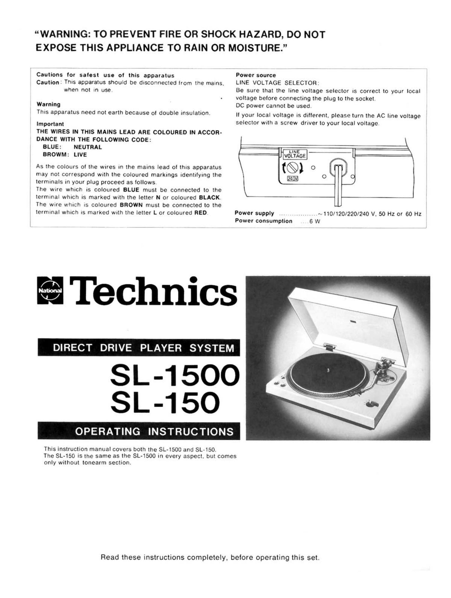
Technics SL 1500 Owners Manual

This is the 6 pages manual for Technics SL 1500 Owners Manual.
Read or download the pdf for free. If you want to contribute, please mail your pdfs to info@audioservicemanuals.com.

Page: 1 / 6
left right
Technics SL 1500 Owners Manual

Extracted text from Technics SL 1500 Owners Manual (Ocr-read)


Page 1

WARNING: TO PREVENT FIRE OR SHOCK HAZARD, DO NOT
EXPOSE THIS APPLIANCE TO RAIN OR MOISTURE.

Cautions tor salest use of this apparatus

Caution: This apparatus should be dlSCOnneCIed from the malnS,

when not m use

Warning
This apparatus need not earth because of double insulation.

Important
THE WIRES IN THIS MAINS LEAD ARE COLOURED IN ACCOR-
DANCE WITH THE FOLLOWING CODE:

BLUE: NEUTRAL

BROWM: LIVE

As the col0urs oi the Wires in the mains lead ol this apparatus
may not correspond With the coloured markings identifying the
terminals in you plug proceed as follows

The Wlfe which IS coloured BLUE must be connected to the
terminal which IS marked With the letter N or coloured BLACK
The Wife which IS col0ured BROWN must be connected to the
terminal which IS marked wrth the letter L or coloured RED

Technics

DIRECT DRIVE PLAYER SYSTEM

SL-15O

OPERATING

This instruction manual covers both the SL-1500 and SL-150.

INSTRUCTIONS

Power source

LINE VOLTAGE SELECTOR:

Be sure that the line voltage selector IS correct to yOur local
voltage belore connecting the plug to the socket

DC power cannot be used

ll your local voltage IS dullerent, please turn the AC line voltage
selector wuth a screw driver to your local voltage

LINE -L
VOLTAGE

(@100

LO

Power supply
Power consumption

«.110/120/220/240 V. 50 Hz or 60 Hz
6 W

The SL450 is the same as the SL-1500 in every aspect. but comes

only without tonearm section.

Read these instructions completely. before operating this set.

Page 2

We want to thank you for selecting the SL-1500/SL-150, DIRECT DRIVE PLAYER SYSTEM.
For optimum performance, we recommend that you read these instructions carefully.

1 PARTS IDENTIFICATION

Hinge

AC power wire

Screw

Turntable mat

Turntable platter

Motor shalt
(turntable shalt)

Strobe dots

Strobe mark

Strobe illuminator/
pilot lamp

i
I
i
I
l
i
l
I
I
l
l
77
I

Output terminals

MODEL SL-1500

Pitch control knobs

The SL-150 is specially designed for SME improved tonearm or
others.
So install a tonearm according to the instructions of your tonearm.

MODE L SL-1 50


Arm base

MODEL SL-1 50

Player case

Ground wire

Balance weight

Stylus pressure ring

Anti-skating knob

Cueing lever

Arm rest

Arm clamp

Tubular arm

Locking nut

Speed/power knob

Head shell
Fig. 1-1
2 BEFORE USE
ocnecx THE PARTS iSL-1500i lSL-150l
Player unit .................. 1 Player unit ................ 1
Dustcover................ . . . ,1 Dustc0ver .................... 1
Turntable platter . . ........ 1 Turntable platter . .1
Turntable rnat .......... , ..... 1 Turntable mat .................. 1
45 rpm. adaptor . ..1 45 rpm. adaptor . , .1
Special oil ................ 1 Special oil ................... 1
Balance weight ............... 1 Arm base ............... 1
Head shell ..................... 1
Overhang gauge ,,,,,, . ...1

OREMOVE THE SHIPPING SCREWS
Remove the two shipping screws and place them in the retaining
holes for future use, when the player must again be transported.
(See Figs. 2 and 3)

/ 2!!

Shipping screws

F-'

/
Retaining holes

£393