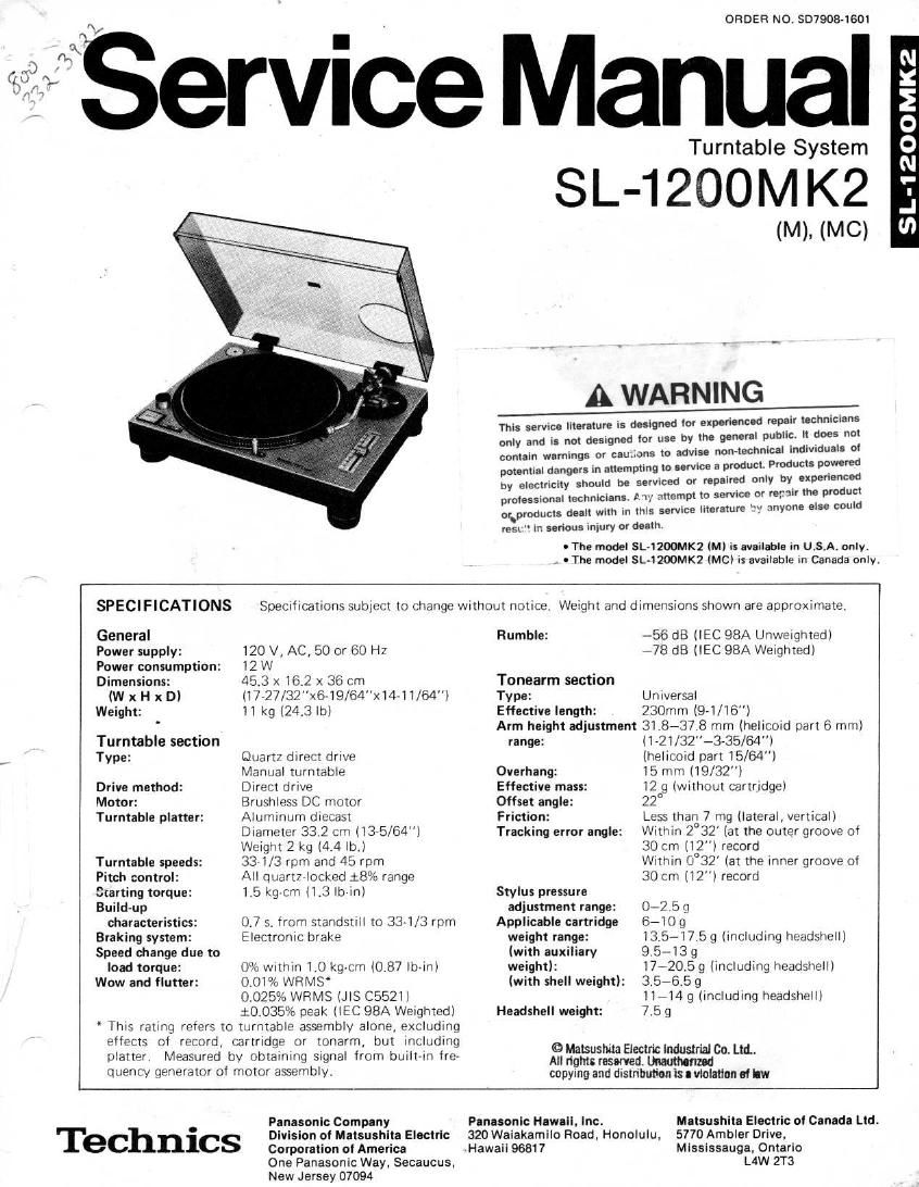
Technics SL 1200 Mk2 Service Manual

This is the 20 pages manual for Technics SL 1200 Mk2 Service Manual.
Read or download the pdf for free. If you want to contribute, please mail your pdfs to info@audioservicemanuals.com.

Page: 1 / 20
left right
Technics SL 1200 Mk2 Service Manual

Extracted text from Technics SL 1200 Mk2 Service Manual (Ocr-read)


Page 1

.
A}

ORDER NO. 807908-1601

Service Manual

Turntable System

SL-1200M K2

(M), (MC)

A WARNING

This service literature is designed (or experienced repair technic
only and is not designed lor use by the general public, it does not
or cau.ions to aowse non-technical indiwduals at
service a product. Products powered
only by experienced
or rerair the product
3! anyone else could

lens

contain warnings
potential dangers in attempting to .
by electricity should be serviced or repaired
professional technicians. 1 'l', attempt to service
or.products dealt with in this service literature
rest in serious iniury or death

- The model SL-I2OOMK2 (M) is available in U.S.A. onlyt
- The model SL-l200MK2 (MCI is available in Canada only.

SPECIFICATIONS

General
Power supply:
Power consumption:
Dimensions:

(W x H x D)
Weight:
Turntable section
Type:

Drive method:
Motor:
Turntable platter:

Turntable speeds:
Pitch control:
Starting torque:
Build-up
characteristics:
Braking system:
Speed change due to
load torque:
Wow and flutter:

Specifications subiect to change without notice. Weight and dimensions shown are approximate.

120 V, AC, 50 or 60 Hz

12 W

45.3 X 162 x 36 cm
(l7-27/32"x6~19/64"x1441/64)
ll kg (24.3 lb)

Quartz direct drive

Manual turntable

Direct drive

Brushless DC motor
Aluminum diecast

Diameter 332 cm (13»5/64)
Weignt 2 kg (4.4 lb.i

33 US rpm and 45 rpm

All quart7 locked 18% range
1.5 kgcm (1.3 Ib-in)

0.7 s. trom standstill to 3371/13 rpm
Electronic brake

0% Within 1.0 kg-cm (0,87 loin)
0.01% WRMS

0.025% WRMS (JIS C5521)
10.035% peak (IEC 98A Weightedi

' This rating refers to tarntablt: assembly alone, excluding
elfects of record, cartridge or tonarm, but including
platter. Measured by obtaining signal from built-in ire-
quency generator of motor assembly.

Rumble:

Tonearm section

Type:

Effective length:

Arm height adjustment
range:

Overhang:

Effective mass:
Offset angle:
Friction:

Tracking error angle:

Stylus pressure
adjustment range:
Applicable cartridge
weight range:
(with auxiliary
weight):
(with shell weight):

Headshell weight:

© Matsushita Electric industrial Co. Ltd.
All right: reserved. zed
copying and distribution is a violation of kw

~56 dB (lEC 98A Unweigtited)
-78 dB (IEC 98A Weighted)

Universal

230mm (9-1/16)

31.87378 mm (helicoid part 6 mm)
(1721/32"-3-35/64"l

(helicoid part 15/64")

15 rrim(19/32i

l2 9 (without cartridge)

22°

Less than 7 mg (lateral, vertical)
Within 2°32 (at the outer groove of
30 cm (12") record

Within 0°32' (at the inner groove Cl
30 cm (12") record

0-2513

67109

13.5-17.5 9 (including headsliell)
9 5-439

i7-20,5 9 (including headshell)
3.5-6.5g

11-14 9 (including headshelll
7.59

Panasonic Company

Division at Matsushita Electric
Corporation at America

One Panasonic Way. Secaucus,
New Jersey 07094

Technics

Panasonic Hawaii. Inc.
320 Waiakamilo Road. Honolulu,
Hawaii 96817

Malsushila Electric ol Canada Ltd.
5770 Ambler Drive.
Mississauga. Ontario

L4W 2T3

Page 2

IV: -3

nly.

l CONTENTS

DISASSEMBLY PROCEDURE ......................... 2,
PARTS IDENTIFICATIONS ...........
ARM BASE ASSEMBLING PROCEDURE.
FEATURES ........................
ADJUSTMENTS
SCHEMATIC DIAGRAM
REPLACEMENT PARTS LIST (Electnca . . . .
TROUBLE SHOOTING .............................. 1

.xl
owmmmbuw

I DISASSEMBLY PROCEDURE

How to remove panel cover
1. Remove head shell and turntable.
2. Secure arm with arm clamp.
3. Remove 5 screws 6 of the panel cover as shown in
Fig. 1.

How to remove stater frame coil and F.G detector
coil
4. Remove 3 connectors ® and 2 read wires G from
power transformer as shown in Fig. 2.
5. Remove 3 screws @ of the drive circuit board and 3
screws 6 of the stater frame cover as shown in Fig. 2.
6. Disconnect 18 soldered parts 6 of the stater coil and
4 soldered parts 6 of the F.G detector coil as show in
Fig. 3.
7. Remove 3 screws 6) of the stater frame ass'y as shown
in Fig. 3.

How to remove bottom base assy
8. Remove 4 audio insulators. (Counterclockwise rotation)
9. Remove 17 screws and spacer 0 as show in Fig. 4.

10. Remove 11 screws 9 as shown in Fig. 4.

How to remove stylus-illuminator lamp

11. Remove 2 screws 0 of the stylus-illuminator lamp
ass'y as shown in Fig. 5.

12. Remove 1 screw 0 as shown in Fig. 6.

How to remove neon-illuminator LED.

13. Remove 4 screws w as shown in Fig.5.

14. Remove 1 circlip 0 and switch Cam 0 as shown in
Fig. 5.

15. Remove strobo-illuminator case.

How to remove tone arm

16. Remove 4 screws 13 of the arm base cover as shown in
Fig. 5.

17. Remove 2 screws 6 of the phone cord clamper as
shown in Fig. 5.

18. Remove phono cord clamper as shown in Fig. 7.

19. Remove 2 screws 13 of the phone cord pcb. as shown
in Fig. 8.

20. Remove 2 screws 9 as shown in Fig. 8.

21. Remove 2 screws 0 of the silicon oil dumper as shown
in Fig. 8.

22. Remove 3 screws Q as shown in Fig. 8.

23. Remove 2 screws 0 of the tone arm as shown in
Fig. 9.

E]

PRINTED CIRCUIT BOARD .
ADJUSTMENT (Electrical) ..........................
REFERENCE VOLTAGE AND WAVEFORM AT EACH IC

BLOCK DIAGRAM. 15,16
EXPLODED VIEWS .............. 17,18
REPLACEMENT PARTS LIST iMechani 19
EXPLODED VIEWS ............................... 20

70mm