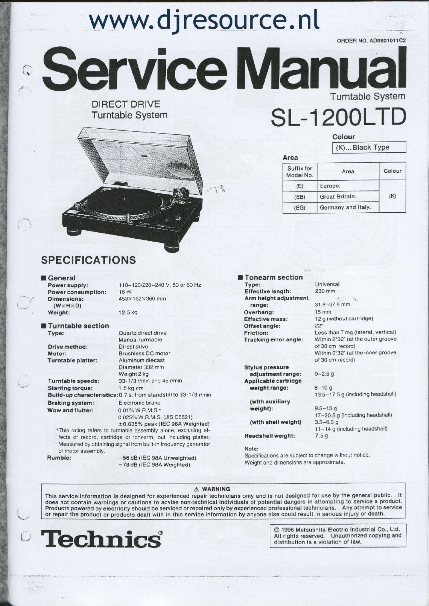
Technics SL 1200 STD Service Manual

This is the 30 pages manual for Technics SL 1200 STD Service Manual.
Read or download the pdf for free. If you want to contribute, please mail your pdfs to info@audioservicemanuals.com.

Page: 1 / 30
left right
Technics SL 1200 STD Service Manual

Extracted text from Technics SL 1200 STD Service Manual (Ocr-read)


Page 1

www.d j resource. nl

ORDER NO. A09601011C2

Service Manual

DIRECT DRIVE
Turntable System

SPECIFICATIONS

I General
Power supply:
Power consumption:
Dimensions:

(W x H x D)
Weight:

I Tu rntabie section
Type:

Drive method:
Motor:
Turntable platter:

Turntable speeds:
Starting torque:

Build-up characteristics:

Braking system:
Wow and flutter:

of motor assembly.
Rumble:

110-120;?20-240 V. 50 or 60 Hz
I6 W
453X162><360 mm

12.5kg

Quartz direct drive
Manual turntable

Direct drive

Brushiess DC motor
Aluminum diecast
Diameter 3:32 mm
Weight 2 kg

33-1/3 2min and 45 r/min
1 .5 kg-cm

0.7 s. from standstill to 33-1/3 r/min

Electronic brake
0.01 as W.R.M.S.'
0.025% W.R.M.S. (JIS 05521)

$013357: peak (IEC 98A Weighted)
'Tiiis rating refers to turntable assembly alone. exc'uding el-
ects of record, cartridge cr :onea'm, out including platter.
Measured by obtaining signal from built-in frequency generator

-56 dB (lEC 98A Unweighted)
-78 dB ilEC 98A Weighted)

Turntable System

SL-1200LTD

Colour
(K)...Black Type
Area
33:: Lo; Area Colour
(E) Europe.
(EB) Great Britain. (K) I
b (EGl Germany and Italy.

I Tonearm section

Type:

Eilective length:

Arm height adjustment
range:

Overhang:

Effective mass:

Offset angle:

Friction:

Tracking error angle:

Stylus pressure
adjustment range:

Applicable cartridge
weight range:

(with auxiliary
weight):

(with shell weight)

Headsheli weight:

Note:

Universal
230 mm

31 8-31.23 mm

15 mm

12 9 (without cartridge]

22°

Less than 7 mg (lateral, vertical)
Within 2°32' (at the outer groove
of 30 cm record)

Within 0°32' (at the inner groove
of 30 cm record)

0-2.5 g

6- 10 g
13.5-17.5 9 (including headshell)

9.5-13 g

17-20.:3 9 (including headsheil)
3.5-6.5 g

11 - 14 9 (including headsheli)
7.5 9

Specifications are subject to change without notice.
Weight and dimensions are approximate.

A WARNING

This service information isdesigned for experienced repair technicians only and is not designed for use by the general public. It
does not contain warnings or cautions to advise non~technical individuals of potential dangers in attempting to service a product.
Products powered by electricity should be serviced or repaired only by experienced professional technicians. Any attempt to service
or repair the product or products dealt with in this service information by anyone else could result in serious injury or death.

i9 Technic§

© 1996 Matsushita Electric industrial 00.. Ltd.
All rights reserved. Unauthorized copying and
distribution is a violation of law.

Page 10

J SL-12OOLTD

- Check the drive control P.C.B. and
power supply P.C.B. as shown below.

Drive :cntrol P.C.B.

Power supply P.C.B /"\\_%\

I Main Component Replacement Procedures

@1131?) 6 (Black)

[xma l-BJFZ]

Remove the panel cover assy.

Remove the / Wt \
drlve COl'ltlOl / ConnectorlCN102)

P'C'B ConneC'nrQCNl 03}

1. Replacement for the drive coil cover and drive coil ass y f
MI 0 X 2-
- Follow the @1- m) ofthe item 1 in checking p'ocedure
for each P.C.B. on page 10. F<
an em -_ !
(3x 3 Remove the 3 connectors. \3 Remove the
W spacer.
, 13:9 //(,~V .k
Removal of the connector ' 0 J \ [g » 9%:
- Release the claws, and 3359/; /j]
then pull out the connector. \ 4» ffC/fix
.\ \ // ///.
\\,,,
J
@1311) e
[XTBS+&J]

»3)_mnmm o
gSFXGO20-02] (Black)

om

[XTW3+8 T]

Page 17

I SCHEMATIC DIAGRAM

Note: 0 S201 :SPEED SELECTOR (33 rpm) switch.
0 S202 : SPEED SELECTOR (45 rpm) switch.
0 8203 : START/STOP switch.
0 8301 : PITCH CONTROL RESET switch in "OFF" position. (interlocked with VR303)
O 8302 : PITCH RESET switch in OFF position.
0 S401 : STYLUS lLLUMlNATOR switch in ON position.
0 8601 : POWER switch in "ON position.
0 S602 : VOLTAGE SELECTOR switch.
0 VR201 : BRAKE ADJUSTMENT VR.
0 VR301 : PITCH CONTROL i 0% ADJUSTMENT VR.
0 VR302 : PITCH CONTROL GAIN ADJUSTMENT VR.
0 VR303 : PITCH CONTROL ADJUSTMENT VR. (lnterlocked with 8301)

ll -_ __--.__

SL-1200LTI

O The voltage value and waveforms are the reference voltage of this unit measured by DC electronic voltmeter

(high-impedance) and oscilloscope on the basis of chassis.

Accordingly, there may arise some error in voltage values and waveforms depending upon the internal

impedance of the tester or the measuring unit.
0 Important safety notice:

Components identified by A mark have special characteristics Important for safety. When replacing any of

these components, use only manufacturer's specified parts.
NO MARK : Voltage when at a stop
( ) : Voltage during rotation
0-)- : +B Line .
O The supply part number is described alone in the replacement parts.

Ref. No. Production Part No. Supply Part No.
Qt 2501265-0PO 2801 265-0
0204A MA165TA MA165

O This schematic dlagram may be modified at any time with the development of new technology.

0 Terminal guide of ICS, transistors and diodes

TC401 IBP

'ANseaz ascaeaalsru

AN6680

AN6675

2301265-0PQ

MA4051 MTA
Ca
% Cathode
/
A / Anode I 7;-
éé/ E > Cathode
E / A {7 gaz 4
C 3 3 ._, Anode Anoae Ce A -®'- Ce
D2SBA20 SVDPRSQCES-Q
xréfli '\
{,1 I." .3' J)
{1:0 , Anode
0" I j ". Camoae
u \ __
& ~ 7 l \\ Lu

' ,.__-1r-m;_-.m m-vw'v-QJ