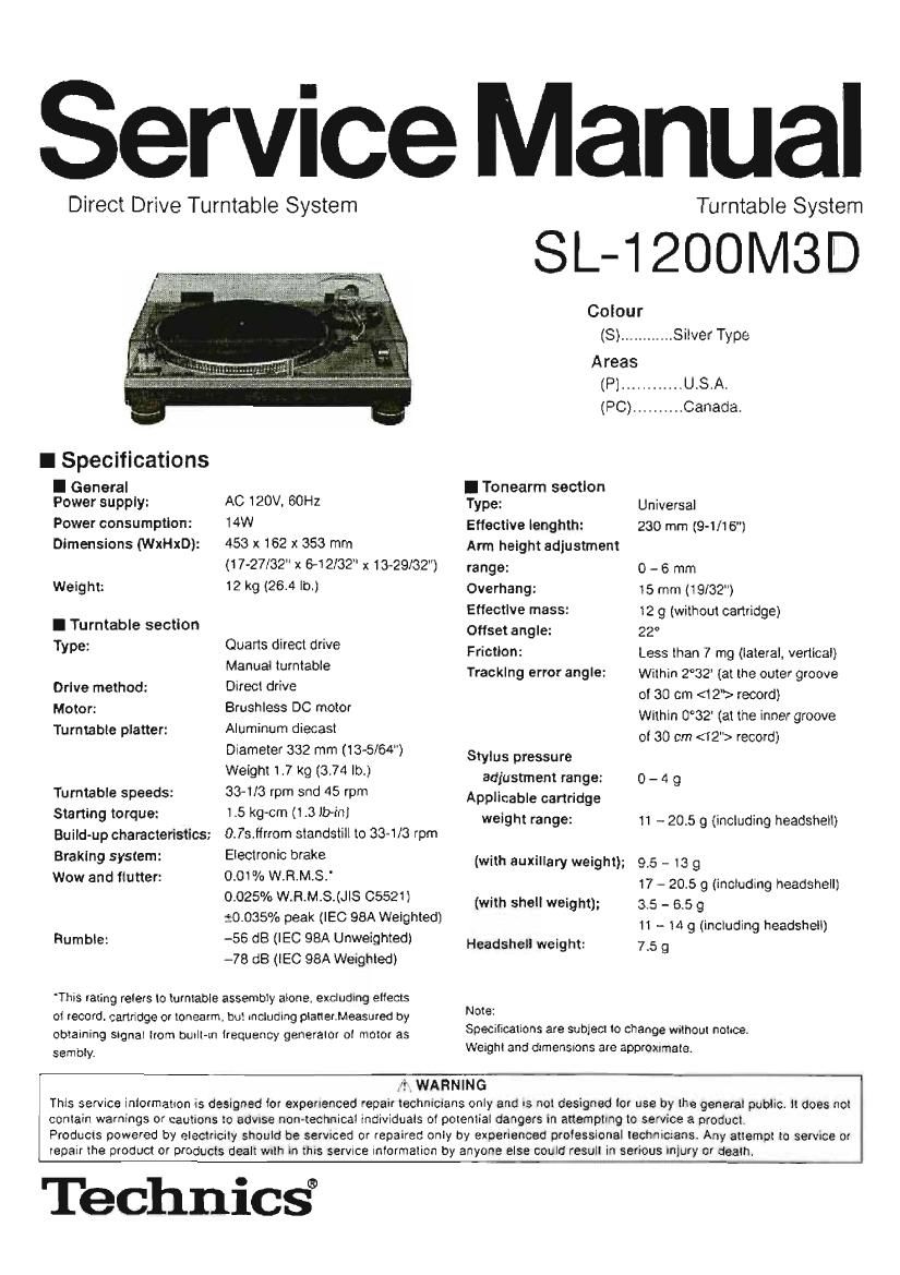
Technics SL 1200 M 3 D Service Manual

This is the 33 pages manual for Technics SL 1200 M 3 D Service Manual.
Read or download the pdf for free. If you want to contribute, please mail your pdfs to info@audioservicemanuals.com.

Page: 1 / 33
left right
Technics SL 1200 M 3 D Service Manual

Extracted text from Technics SL 1200 M 3 D Service Manual (Ocr-read)


Page 1

Service Manual

Direct Drive Turntable System Turntable System
Coiou r
(S) ........... Silver Type
Areas
[P] ............ USA.
(PC) .......... Canada.
I Specifications
I General I Tonearm section
Power supply: AC 120V. SOHZ Type: Universal
Power consumption: 14W Efleotlve lenghth: 230 mm (9-1/15")
Dimensions (WxHxD): 453 X 162 X 353 mm Arm height adiustment
(17-27/32" x 6-12l32 x 13-29/32") range: 0 - 6 mm
Weight: 12 kg (26-4 lb.) Overhang: 15 mm (19/32)
Effective mass: 12 9 (without cartridge)
I Turntable section offset angle: 22°
TYPE: Ouaits direct drive Friction: Less than 7 mg (lateral. vertical)
Manual turntable Tracking error angle: Within 2°32 (at the outer groove
Drive method: Direct drive oi 30 cm <1 2"> record)
MOW" Bruehless DC motor Within 0°32 (at the inner groove
Turntabie piatter: Aluminum dtecast of 30 cm (12") mow)
Diameter 332 mm (13-5/64") Stylus pressure
Weight 1.7 kg (3.74 lb.) adjustment range: 0 _ 4 g
Turntable speeds: 33-118 rpm and 45 rpm Applicable cartridge
Starling torque 1.5 9 (1-3 '5) weight range: 11 - 20.5 9 (including headshetl)
Build-up characteristics: 0.73.lirrom standetill to 33-1/3 rpm
Braking system: Electronic make (with auxiliary weight); 95 - 13 9
Wow and flutter: 00W: W-R-MS' 17 - 20.5 9 (including headshell)
0025/0 W.H.M.S.(JIS 6552)) (with sheliweight); 3.5 _ 55 9
20035? peak (IEO 98A Weighted) 11 h 14 9 (including headshell)
Rumble: -56 dB (IEC 98A Unweightedi Headshell weight: 7.5 g
-78 dB (lEC 98A Weighted)
Thls rating relers to turntable assembly alone, excluding aliens
Note:

at record. cartridge or tonearm, but, including planervMeasured by
obtaining signai lrom Dulllstn lrequency generator oi motor as
Sembly:

Specifications are subject to change without notice.
Weight and dimensions are approxrrnatet

J? WARNING
This service information is designed for experienced repair technmlans only and Is nol designed tor use by lhe general public it does not
contain warnings or cautions to advise non-technical individuals of potential dangers in attempting to service a product.
Products powered by electricity should be serviced or repaired only by experienced prolessional technicians. Any attempt to service or
repair the product or products deal: wrth in this service iniormation by anyone else could result in serious injury or death.

Technicsi

Page 2

l Contents

- Safety Precaution .
- Accessories.
- Features ..
- Controls ..
- Preparation of the cartridge...
- Putting the player together
- Connections and Installation.
- Preparatory adjustments .......
- Playing records...............................
- Adjustments while using the unit.. .
- Maintenance .. . 10
- Product service ....................................................... 10

U
m
(a

m


(ocean-Amounts)

Pagt
- Troubleshooting guide .. 11
- Operation Checks and
Component Replacement Precedures 12-16
- Schematic Diagram .......................................... 17-19
- Printed Circuit Boards ..... . ............... . 20-22
- Measurements and Adjustments....
- Block Diagram .......................
- Wiring Connection Diagram.
- Repracement Parts Llst..
- Cabinet Parts Location.

. Packaging .......................

I Safety Precaution (This Safety Precaution" is applied only in U.S.A.)

UNg

we.

being exposed to a shock hazard.

o INSULATION RESISTANCE TEST

. Beore servicing, unplug the power cord to prevent an electric shock
When replacing parts, use only maanutaacturers recomended wrnoonents tor safety.
. Check the eardrum at the power cord. Replace i! wear or damage is evident.
After semiong. be sure to restore the lead dressjnsulation barriers. Insulation pape's. sh etdsetc.
Betnre 'etumlng the serviced equipment to the customer. be sure to nature the icllcwing insulation resrstance test to prevent the customer tram

1. Unoiug l'le pflweir cord and short the two prongs ol the plug will a lumber Wile.

2. Turn on the power awn-2h.

3. Measure the resistance value with onrnmeier between the iumpered AC plug and each exposed metal cabinet pan, such as screwheads antenna
control shafts. handle brakats. etc Equipment wrth antenna terminals should read between 3 Mn and 5.2 M5? to all exposed parts. (Fig, A)
Equenmerl Without antenna terminals should read approxrmateiy infinity to all exposed parts. iFlg. Eli

Note: Some exposed pans may be isolated lrom the chassis by design. These will read lnll'nity.

Antenna
terrn flat

\Hr

at 9
Exposed /
metal part b if
(FigA)

Ftemszance = 3 Mn - 5.2 MB

Exposed / (_
metal part

Ohmrnetor
(Fig. B)

Resrstance - Approx 95

4 H the measmemenl lS Outside the Saeotled iimlls. there is a cosgrbil ty ot a shock hazard. The equipment should be repaired and :ect'ecked beton

ii is returned to the customer.

I Accessories SronlyforLleA.)

0 order accessories contact 1-800-332-5368 or web site (http: Irwwwpanasoniocom).

Turntable .................. 1 pc.
(SFI'E172-01Z)

Dust cover ............... 1 pc.
(SFADtZZ-Ot A)

Shell with stylus weight
(SFPOCailODfiK) ......... 1 pc.

Disc slip sheet set ...... 1 pc.

(36800051)
-Disc slip sheet
-Transparent sheet

3%

Balance welght ......... 1 pc.
(SFPWGt 7201K)

Auxiliary weight ......... 1 pc. Screw set for cartridge......1 pc..

(SFPWGt7202) -Nuts(RHN25003)
@ -Screwe-short(SFCZV8801)
-Screws-long[5FPEV5801)
EP record adaptor......1 pc. -Washers(SFPEW9801J
(SFWEOtO)
@ §
3
Shell weight .............. 1 pc.
(SFFZBSSO!)
0 V A cartridge is not includefl
Overhang gauge ......... 1pc.
(SFKO13501)

m

/J

Page 3

mus-4:- - , u - "

(Stylus weight?)
Screw lor
cartridge

, Shell with
stylus weighl


Lead wire
'5 Termmal

.r " N t
Stylus N9 0- U

Screw lor cartridge

/Ovemang
Stylus tip 4: 7 / gauge

A ~-- 52mm -a

1:1
8

YES

l Features

A masterpiece amongst turntables with e worldwide repute-

tlon.

Pilcll control reset button

o Pitch (an be instantly reset to the raled speed (33 V3 or 45 rpm).

Highly accurate tumtable speed maintained continuously

with a quartz pitch control

. The pitch can be varied between -6 and +59%. with accuracy main-
tained throughout the range.

The direct drive produces high torque

. Wow and flutter below 0.01%. Staning torque oi l.5 kg/cm enabling
the turntable to reach 33 1I3 rpm in 0.7 seconds.

a Fully electric braking system.

Tone arm with glmbat suspension

. The lone arm can be lmely adjusted to a range at 6 millimeters With the
lockable height control,

Anti-vibration design with a layer cabinet construction and

large insulating legs.

Pop-up stylus light.

I Controls n

No. Name Reference pagels)
® EP record adaptor ...... . ...................... 8
(2 Turntable base ............................ 3
©Turntabiemat (Ordlsc slipsheet) 4
(9 Center spindle ................................ 4
(5) Turntable ..................................... 4
@Strobelighis ....................... . ..... 9
® Power switch (power ) .......................... 8
(El Strobe llliuminatorlpllot lamp ..................... 9
£5) Start/stop button (start - stop) ................... 3
0} Speed select buttons (33, 45) .................... 8
® Arm-height control .............. . .............. 7
([0 Shell stand ......... . ......... .. . . ............ a
a} Balance weight ................................ 4
® Stylus pressure control ......................... 6
d3) Arm lock ..................................... 7
® Anti-skating control ............................ 6
@Cuelevar.......... ........................... 6
®Armciamp 6
(9 Arm rest ...................................... 8
@Tonearm...... ............ . .................. 4
@ LED indicator ................................. 9
@PltchcontroHPltchedJ.) ............ 9
® Locking nut .............................. 4
@Resetbuttonfleeet)

Q Head shell . ....................

® Stylus light switch .......... . ........

GD Stylus light ................................... a

l Preparation of the cartridge E

Attach a cartridge (not included).

Follow the cartndge's instructions to correctly attach It to the bean

shell.

I Use the Included shall weight " when usrng a light cartridge [3.5
to 5.5-, grams).

- Use rhe stylus weight '3 to increase stylus pressure ! up page 6).
Leave Ii. oil until. stylus pressure has Been adjusted.

Adjust the overhang.

Fit the included overhang gauge to the head shell. Adjust the over»
hang and lacung oi the cartridge and lighten the screws.

0 Line the paint oi the stylus up With the end at the gauge.

- The camvne shout.T be parallel on the shell head.

Page 23

l Measurements and Adjustments

NOKES: - Make the lollovwmg adjustments alter replacing parts such as IC's. Transistors. Diodes. etc.

- Condition ot the set.

1.1Power switch. ...ON
2.:Pitch contro:l.. ...Center position
3.8peed selector switch ............. 33 r.p.m.
- tnstruments to be used
1.Tester
2.Frequency counter
' Parts
Adjustment I Cannactton adjusted Procedure
l
; Frequency counter t. Conner: the lrequency counter and turn the power supply ON.
1 pIICh control 1 0% M TP27 VHSOI 2. Set the pttch control knob to 0".
adjustment I (-l . Earth point (Fig. 1) (Indicator lights um
I 3. Adjust VR301 so that the lrequency rs 26208 «Hz 1- 0 05 kHz.
1, Set the pitch control knob to '0'.
Tester 2. Pull out the connector CN102 of drive P.C.B.
2 Pitch control gain l+) CNIoz 16mm, @ V8302 3. Connea the tester to tetmtnais.® and (E) at connector CN102
" adjustment (-l CNIOZ terminal (9 (FIQ- 2) on the pitch control RCB. Side.
4. Adtust VR302 so that the resustance value at the tester l5
2.875 1 0,25 kn. 7 7
VR201 1. Adjust VR201 so that the rotation at 33 r.p.m. stops withrn
3 Brake autustment . ,
(Fig 1 the angle 0' 30" ~ 210 alter depressang the stop posrtion.

0 Alignment Points

Please reIer to Printed Circuit Board Diagram tor test point locations.

DRIVE F'.C.B.

men comm
i- 0% ADJUSTMENT

PITCH CONTROL
P.C.B


PITCH CONTROL
GAIN ADJUSTMENT

Ell/-