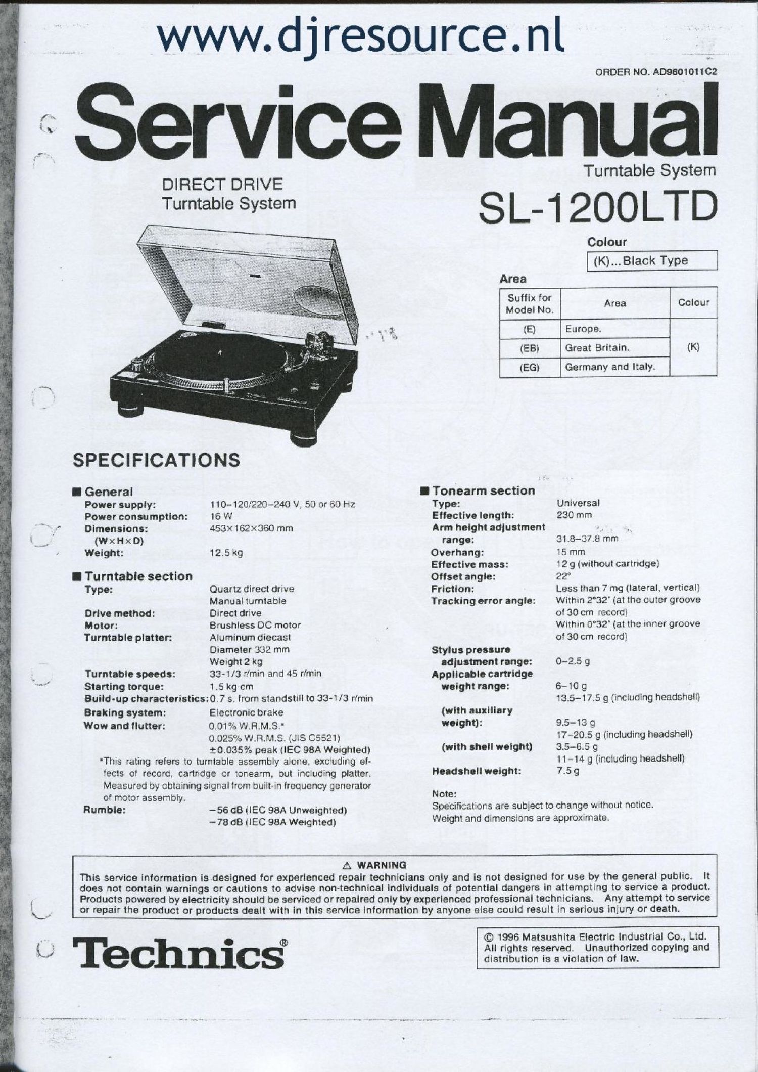
Technics SL 1200 LTD Service Manual

This is the 30 pages manual for Technics SL 1200 LTD Service Manual.
Read or download the pdf for free. If you want to contribute, please mail your pdfs to info@audioservicemanuals.com.

Page: 1 / 30
left right
Technics SL 1200 LTD Service Manual

Extracted text from Technics SL 1200 LTD Service Manual (Ocr-read)


Page 1

www.d j resource. nl

ORDER NO. A09601011C2

Service Manual

DIRECT DRIVE
Turntable System

SPECIFICATIONS

I General
Power supply:
Power consumption:
Dimensions:

(W x H x D)
Weight:

I Tu rntabie section
Type:

Drive method:
Motor:
Turntable platter:

Turntable speeds:
Starting torque:

Build-up characteristics:

Braking system:
Wow and flutter:

of motor assembly.
Rumble:

110-120;?20-240 V. 50 or 60 Hz
I6 W
453X162><360 mm

12.5kg

Quartz direct drive
Manual turntable

Direct drive

Brushiess DC motor
Aluminum diecast
Diameter 3:32 mm
Weight 2 kg

33-1/3 2min and 45 r/min
1 .5 kg-cm

0.7 s. from standstill to 33-1/3 r/min

Electronic brake
0.01 as W.R.M.S.'
0.025% W.R.M.S. (JIS 05521)

$013357: peak (IEC 98A Weighted)
'Tiiis rating refers to turntable assembly alone. exc'uding el-
ects of record, cartridge cr :onea'm, out including platter.
Measured by obtaining signal from built-in frequency generator

-56 dB (lEC 98A Unweighted)
-78 dB ilEC 98A Weighted)

Turntable System

SL-1200LTD

Colour
(K)...Black Type
Area
33:: Lo; Area Colour
(E) Europe.
(EB) Great Britain. (K) I
b (EGl Germany and Italy.

I Tonearm section

Type:

Eilective length:

Arm height adjustment
range:

Overhang:

Effective mass:

Offset angle:

Friction:

Tracking error angle:

Stylus pressure
adjustment range:

Applicable cartridge
weight range:

(with auxiliary
weight):

(with shell weight)

Headsheli weight:

Note:

Universal
230 mm

31 8-31.23 mm

15 mm

12 9 (without cartridge]

22°

Less than 7 mg (lateral, vertical)
Within 2°32' (at the outer groove
of 30 cm record)

Within 0°32' (at the inner groove
of 30 cm record)

0-2.5 g

6- 10 g
13.5-17.5 9 (including headshell)

9.5-13 g

17-20.:3 9 (including headsheil)
3.5-6.5 g

11 - 14 9 (including headsheli)
7.5 9

Specifications are subject to change without notice.
Weight and dimensions are approximate.

A WARNING

This service information isdesigned for experienced repair technicians only and is not designed for use by the general public. It
does not contain warnings or cautions to advise non~technical individuals of potential dangers in attempting to service a product.
Products powered by electricity should be serviced or repaired only by experienced professional technicians. Any attempt to service
or repair the product or products dealt with in this service information by anyone else could result in serious injury or death.

i9 Technic§

© 1996 Matsushita Electric industrial 00.. Ltd.
All rights reserved. Unauthorized copying and
distribution is a violation of law.

Page 4

SL-1 200LTD \

Before use

Caufion:

Never connect the AC power plug before assembly has been
completed.

Attach the dust cover last. so that assembly and adjustments
can be made most conveniently.

Note:

The operating instructions are commonly applicable to units
with cartridge and without cartridge. and also to those of
different colors.

For the units without cartridge. the cartridge section of the
specifications may be neglected.

I Checklist of parts

Turntable unit ........................................ 1
Turntable platter ...................................... 1
Turntable mat ....................................... 1
Dust cover ........................................... 1
45-rpm adaptor .......... . ....................... . . 1
Balance weight ....................................... 1
Auxiliary weight ..................................... 1
Headsheli ............................................ 1
Shell weight ......................... . ................ l
Overhang gauge (for the unit without cartridge) . . ._ ..... 1

Assembly and set-up

I installation of turntable platter

1. Place the turntable platter on the center spindle.
Note:
The rotor is connected to the underside of the turntable
platter. (The magnet of the motor is attached to the turn-
table platter.) To maintain optimum performance. extra
care should be taken to prevent adhesion of dust or iron
filings to the magnet and not to damage the magnet by
dropping it.
Do not remove or loosen the screws. Should the position
of the iixed magnet be altered by loosening the securing
screws. the rated performance of the unit cannot be
guaranteed. (See Fig. 2.)

2. Place the turntable mat on the platter.

I installation of cartridge (See Fig. 3.)

(For the unit without Cartridge)

When you install a cartridge. refer to the operation instruc-

tions of that cartridge.

During installation. attach the stylus protector to guard the

stylus tip from damage.

1. Connect the lead wires to the cartridge terminals.
The terminals of most cartridges are color coded.
Connect each lead wire to the terminal of the same color.

White (L+) ......... Left channei+
Blue (L-) .......... Left channel-
Bod (Flo) ......... Right channol+
Green (R-) ...... Right channel-

2. Install a cartridge to the headshell. and tighten it with
SCleWS provided with the cartridge.
Note:
Use the shell weight only for a lightweight cartridge
(less than 6.0 g ). (See Fig. 0.)

I Adjustment of overhang (See Fig. 5-1.)
(For the unit with overhang gauge)
1. insert the headshell me the gauge.
2. Loosen the mounting screws and move the cartridge
forward or backward until the stylus tip lines up with the
edge oi the gauge.

3. Tighten the mounting screws without moving the car-
trldge.
Note:
Your cartridge is now adjusted for lowest tracking error
and minimum distortion.
This gauge is exclusively designed for this tonearm.

I Adjustment of overhang (See Fig. 5-2.)
(For the unit without overhang gauge)
The overhang of this unit is 15 mm
Loosen the mounting screw and move the cartridge forward
or backward until the distance between the stylus tip and the
plug becomes 52 mm as shown in the picture.
Tighten the mounting screws without moving the cartridge
Adjust horizontal zero balance, stylus pressure and arm-lift
height whenever you change the cartridge.

I Installation of headshell (See Fig. 6.)
insert the headshell into the front end of the tubular arm. and
turn the locking nut clockwise {in the direction shown by the
arrow A). with the headshell iirmly held horizontally.

I Installation of balance weight (See Fig.7.)
Place the balance weight on the rear shaft of the tonearm.

Note:

In case the cartridge weight exceeds 10 9, it is necessary
to fix the attached auxiliary weight over the rear shaft of
the arm.

With this auxiliary weight in use. it is possible to use any
cartridge whose weight is in the range of 9.5-1 3 9. (See
Fig. 8.)

I Adjustments of horizontal zero (0) balance

and stylus pressure

1. Remove the stylus protector. if your cartridge has a
detachable one. Be careful not to touch your fingers to
the stylus tip.

2. Flelease the arm clamp and lift the tonearm from the arm
rest to free it.

3. Turn the entire balance weight clockwise (indicated by
the arrow A) or counterclockwise (indicated by the
arrow 8") until the tonearm is approximately balanced
horizontally (floats freely). (See Figs. 9 and 10.)

Note:

(A)

Excessive forward advancement of the balance weight
causes the cartidge side to be lowered.

(3)

Excessive backward retreatment oi the balance weight
causes the cartridge side to be raised.

(C)

Upon balancing between the balance weight and
cartridge. the tonearm is held horizontal.

During the adjustment oi the horizontal zero (0) balance,
be careful that the stylus tip of the cartridge does not
contact the turntable mat or turntable base.

4. After the tonearm is horizontally zero (0) balanced, tem-
porarily refasten the tonearm with the arm clamp.

5. Hold the balance weight stationary with one hand as
shown in the picture, and rotate only the stylus-pressure
ring to bring the numeral "0" of the ring into alignment
with the center line on the tonearm rear shaft. (See Fig.
11.)

The adjustment of the horizontal zero (0) balance is now
completed.

6. After adjusting the horizontal zero (0) balance, turn the
balance weight clockwise in the direction of the arrow
and align to the correct stylus pressure. (See Fig. 12.)
(Follow the cartridge manufacturer's recommendation.)
As the stylus-pressure ring moves in step with the
balance weight, proper stylus pressure can be selected
by directly reading the graduated ring.