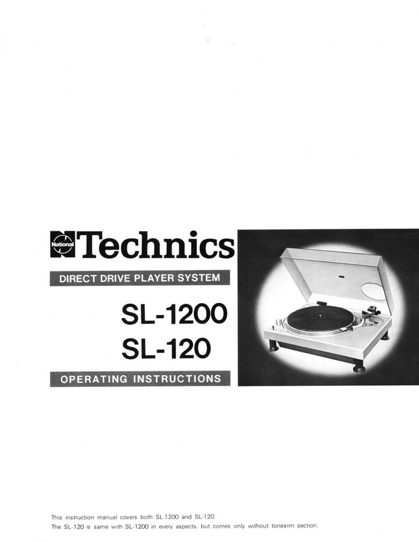
Technics SL 120 Owners Manual

This is the 6 pages manual for Technics SL 120 Owners Manual.
Read or download the pdf for free. If you want to contribute, please mail your pdfs to info@audioservicemanuals.com.

Page: 1 / 6
left right
Technics SL 120 Owners Manual

Extracted text from Technics SL 120 Owners Manual (Ocr-read)


Page 1

ITechnics

SL-1200
SL-120

OPERATING INSTRUCTIONS

This Instruction marmm Covers both SL 1200 and SL 120

The SL 120 15 same Wsth SL 1200 In every aspects. but comes only Wzthout Ionearm SECIIOH

Page 2

AC LINE
VOLTAGE SEL

Fig. 1 Fig. 3
Abb. 1 Abb. 3

We want to thank you for selecting the SL-1200. DIRECT DRIVE PLAYER SYSTEM. To receive optimum performance from this DIRECT DRIVE
PLAYER SYSTEM. we recommend that you read these operating instructions carefully.

PARTS IDENTIFICATION
OPERATION AND FUNCTION OF CONTROLS

(TURNTABLE SECTION)


OSTROBO ILLUMINATOFI (See Fig.1-0)

AC LINE V ' .
OLTAGE (F's 2) When the power switch/speed selector is on. the strobe illuminator is lit.

Make sure that the AC line voltage selector is correct to yOur local volt-
age before connecting the AC power cord.

um" OVARIABLE PITCH CONTROLS (See Fig.1- 0 )
if your local voltage is different, please turn the AC line voltage selector Adjust the "variable pitch controls" if y Tl are designed
to your local voltage. to provide adjustment of the selected speed by 10%'3"Qe.

Select the speed of the turntable platter by setting the "power switch/

ROTOR (308 Fig.1- 0 I speed selector" to the desired position. The rotating turntable platter,
This unit uses a direct drive motor. Therefore, the rotor, which is the when illuminated by strobo illuminator. may show movement of the
rotating part of the motor, is connected directly to the turntable platter. marks on the strobe disc. Adjust the "variable pitch controls" until
The spindle of the motor and the shaft of the turntable platter are the the strobe marks are stationary.
same. For this reason, to maintain the high performance described in After the necessary adjustment has been made. the speed will not
the specifications, it is not desirable to apply a large amount of external change and readjustment will not be necessary.
force to the rotor and the spindle ol the motor. The rotor is. therefore, The strobo marks molded around the turntable platter are used to check
clamped securely to protect the delicate and important parts during the correct speed of rOtation for 50 Hz (European). and 60 Hz IU.S.A.)
transportation. Adjust its rotation according to the strobo label.

Be sure to remove these fittings 0 carefully. and save them for future
use. as when, for example, the player must again be transported.
CAUTION

The rotor of the motor is constructed so that it cannot be removed, in

OSPEED ADJUSTMENT SCREWS (See Fig.1- 0 I
If, for any reason, the adjustment cannot be successfully made, use a
l-I tip screwdriver to adjust the appropriate speed adjustment screw
(33 or 45) located beneath the turntable platter.
Turning the speed adjustment screWs to the right or left will increase

order to maintain its high performance for a long time.
Do nox attempt to remove the removal prevention fitting 9 for the

r0tor. .
or decrease the speed respectively.

OPOWER SWITCH/SPEED SELECTOR (See Fig.1-0)
Set the "speed selector" to the desired position (33 or 45. depending

upon the speed of the record to be played). The strobo illuminator
will be lighted, and the turntable platter will rotate.

OSTROBO MARKS (See Fig.1- 0 I

OSTROBO LABEL (See Fig.1- 0 I