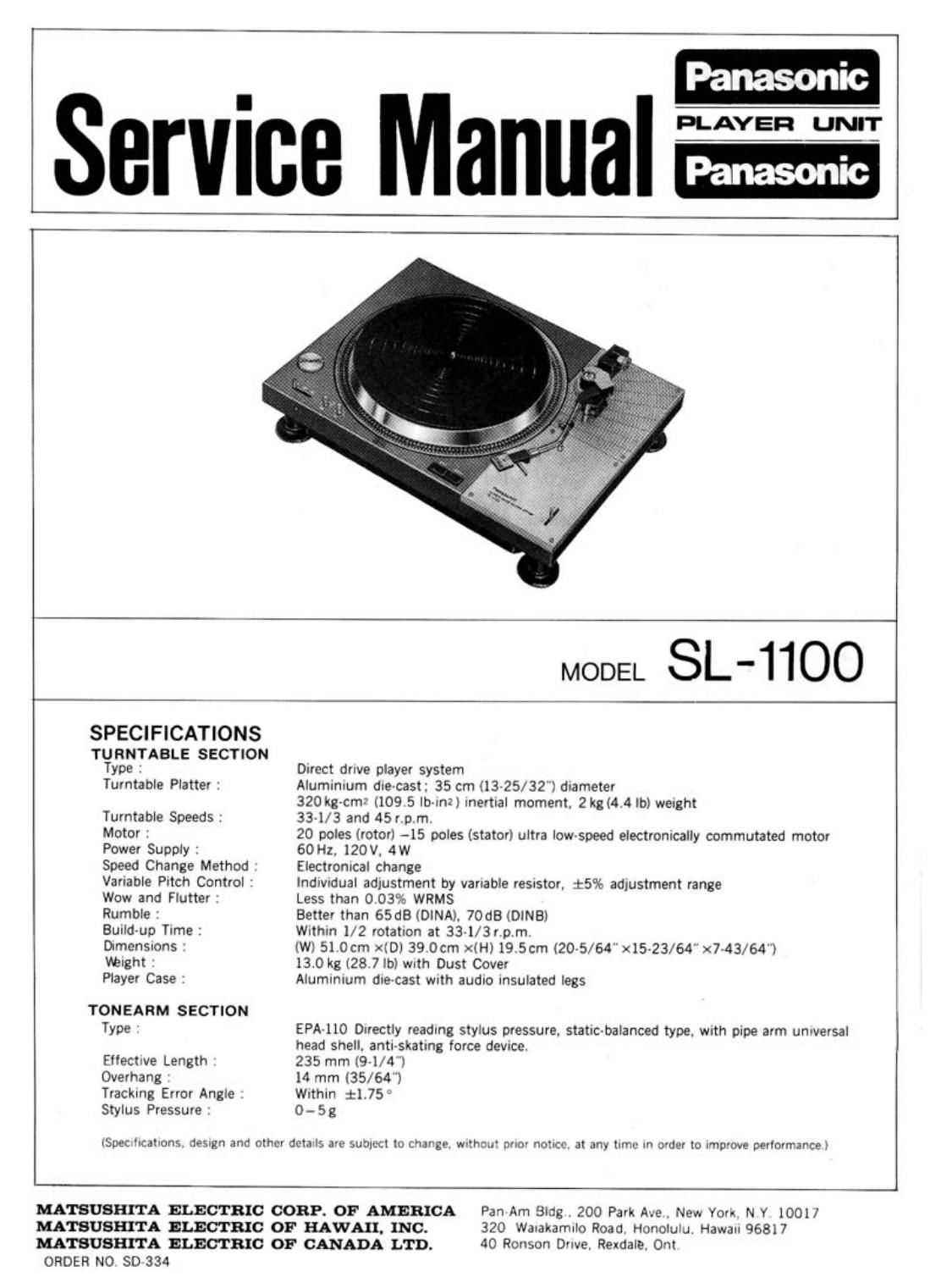
Technics SL 1100 Service Manual

This is the 10 pages manual for Technics SL 1100 Service Manual.
Read or download the pdf for free. If you want to contribute, please mail your pdfs to info@audioservicemanuals.com.

Page: 1 / 10
left right
Technics SL 1100 Service Manual

Extracted text from Technics SL 1100 Service Manual (Ocr-read)


Page 1

Panasonic

Service ManuaIF

MODEL SL-IIOO

SPECIFICATIONS
TURNTABLE SECTION
Type : Drrect dnve player system
Turntable Platter : Aluminrum dre~cast; 35 cm (13-25/32'l drameter
320 kg-cmr (109.5 lb-Ifl?) mertral moment, 2 kgl4.4 lb) werght
Turntable Speeds: 331/3 and 45r p m.
Motor : 20 poles (rotor) -15 poles (stator) ultra lowspeed electronically commutated motor
Power Supply : 60 Hz. 120V, 4W
Speed Change Method Electromcal change
Varrable Prtch Control : Indrvrdual adjustment by variable resrstor. i596 adjustment range
Wow and Flutter Less than 0.03% WRMS
Rumble : Better than 65dB (DINA), 70GB (DINB)
Buuld-up Trme : With-n 1/2 rotation at 33~1/3r,p.m.
Drmensions (W) 510cm XID) 39.0cm le) 19.5cm (205/64" x15-23/64 x743/64"l
Weight : 13.0 kg [28.7 lb) wrth Dust Cover
Player Case : Aluminium dre-cast wnth audio insulated legs
TONEARM SECTION
Type EPA-110 Directly readrng stylus pressure, slam-balanced type, wath pipe arm unwersal
head shell, antirskatmg force devrce,
Ellectrve Length 235 mm (9-1/4")
Overhang 14 mm (35/64)
Tracking Error Angle Wrthln $1.75 ~
Stylus Pressure 0- Sg

ISUeCllCaIlonS. nemgn and other detalls are sumect to change. wnthcut prior notice at any time m order to Improve performance)

MA'ISUSHITA ELECTRIC CORP. OF AMERICA Pan Am Bldg . 200 Park Ave. New You, N Y 10011
MATSUSHITA ELECTRIC OF HAWAII. INC. 320 Waralran'nlo Road. Honolulu. Hawau 968i 7
MATSUBI'II'IA ELECTRIC OF CANADA LTD. 40 Ronson D'Ive, Rexdale. Ont

ORDER N0 50 334

Page 2

CIRCUITRY AND OPERATION PRINCIPLES

The control circuitry of the motor in this set consists of the following circuits; the oscillation circuitry which generates
the input signal of the position detecting section; the switching circuitry which controls the current of the armature
(stator core) winding by the output signal of the position detecting section; and the speed control Circuit. which detects
the voltage generated in the speed generator winding in proportion to the rotation of the motor and keeps the motor
speed constant.

In addition. a DC stabilized power supply is included in order to supply power to each assembly.

BLOCK DIAGRAM OF DIRECT DRIVE PLAYER SYSTEM

OThe oscillation circuitry generates a high-frequency signal of about 50 kHz and supplies it to primary coils W111.
W121 and W131 of the position detecting section.

OThe position detecting rotor of the position detecting section changes. by rotating. the coupling degree between
primary coils W111. W121 and W131 of the position detecting section and the secondary coils (W112. W122 and
W132) of the same section.

OAs shown in the figure. the coupling between W111 and W112 is the closest. and that between W121 and W122 is
less.

OThe high-frequency signal mentioned above is induced to the secondary coil of the closely-coupled section.

.The high-frequency voltage thus induced is rectified by diodes D1. 02. and D3. and. as the position signal. controls
transistors Tm. T83 and TRS of the Switching circuitry.

OPower transistors TR2. TFI4 and TR6 are controlled by TR1. TFI3 and TRS. As shown in the figure. the high-frequency
signal which is generated in W112 is rectified by D1 and this volatge is applied to TR1 . making TRZ in the condition
of continuity.

08y the three circuitry-centinuity/breaking actions of power transistors TR2. TR4 and TR6. current flows through
drive windings W211. W231 and W221 of the armature section. and power for rotation is generated between the
armature and the magnet rotor.

.Speed generation windings W212. W222 and W232 are wound on the drive winding and bifilar, and they generate
three-phase AC voltage which has an amplitude proportionate to the speed.
This voltageis rectified by diodes D4, 05 and 06. and DC voltage Ea. which is proportionate to the speed. is obtained.

OComparing this speed voltage (Ea) with the standard voltage (Es) from the standard voltage section in the voItage
stabilization circuitry. which is determined corresponding to the necessary rotation speed. adjustment is made of the
current which flows through the power transistors of the switching circuitry. In other words. if the speed is faster
than the specified speed. the current decreases and the speed becomes slower. If the speed is slower than specified,
the current increases and the speed increases.

In this way. the speed is stabilized.

OThe speed change and adjustment are made by changing the resistance of the circuitry (that is by changing the
standard voltage) which compares the standard voltage with the speed voltage.