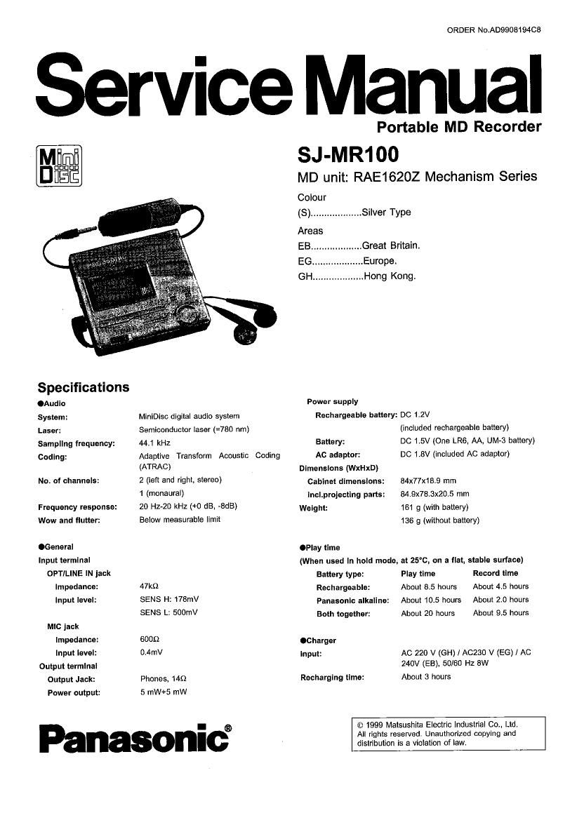
Technics SJMR 100 Service Manual

This is the 75 pages manual for Technics SJMR 100 Service Manual.
Read or download the pdf for free. If you want to contribute, please mail your pdfs to info@audioservicemanuals.com.

Page: 1 / 75
left right
Technics SJMR 100 Service Manual

Extracted text from Technics SJMR 100 Service Manual (Ocr-read)


Page 1

ORDER No.AD9908194CS

Service Manual

Portable MD Recorder
SJ-MR100

MD unit: RAE16202 Mechanism Series

Colour
(8) ................... Silver Type
Areas
EB ................... Great Britain.
EG ................... Europe.
GH ................... Hong Kong.
Specifications
.Audlo Power supply
System: MlnlDisc digital audio system Rechargeable battery: DC 1.2V
Laser: Semiconductor laser (=7Bo nm) (included rechargeable battery)
Sampling frequency: 441 kHz Battery: DC 1.5V (One LR6. AA, UM-3 battery)
Coding: Adaptive Transform Acoustic Coding Ac adaptor: DC 1.8V (included AC adaptor)
(ATRAC) Dimensions (WxHxD)
No. of channels: 2 (left and right, stereo) Cabinet dimensions: 84x77x18.9 mm
1 (monaural) |nc|.projecting parts: 84.9x78.3x20.5 mm
Frequency response: 20 Hz-20 kHz (+0 dB. -8dB) Weight: 161 g (with battery)
Wow and flutter: Below measurable limit 136 9 (without bafiery)
.General OPlay fime
'"PU ermlna' (When used In hold mode, at 25"c, on a flat, stable surface)
OPTIL'NE 'N jack Battery type: Play time Record lime
Impedance: 47kg] Rechargeable: About 8.5 hours About 4.5 hours
PM level: SENS 2 178mV Panasonic alkaline: About 10.5 hours About 2.0 hours
SENS L: 500mV Both together: About 20 hours About 9.5 hours
MIC jack
Impedance: 6009 .Charger
"Wt level: 0,4mv Input: AC 220 v (GH) / A0230 v (EG) / Ac
Output terminal 240V (EB), 50/60 Hz 8W
Output Jack: Phones, 1451 Recharging time: About 3 hours
Power output: 5 mW+5 mW

© 1999 Matsushita Electric Industrial Co., Ltd.

I ®
All rights reserved. Unauthorized copying and
distribution is a violation of law.

Page 2

Notes:
- The play time may be less depending on the operating
conditions.
- Specifications are subject to charge without notice. Weight
and dimensions are approximate.

A WARNING

This service information is designed for experienced repair technicians only and is not designed for use by the general public.

It does not contain warnings or cautions to advise non-technical individuals of potential dangers in attempting to service a product.
Products powered by electricity should be serviced or repaired only by experienced professional technicians. Any attempt to service
or repair the product or products dealt with in this service information by anyone else could result in serious injury or death.

CONTENTS

1 Precation of Laser Diode

2 Accessories

3 Operating Instructions-
4 Handling Precautions for Traverse Deck (Mechanism Unit)-20

41 Mechainsm Unit (optical pickup) ................................... 20
4.2. Caution for repairing of MD mechanism (optical pickup) 20
4.3. Grounding for electrostatic breakdown prevention ---------- 20

5 Operation checks and Main Component Replacement
Procedures --

6 Operating Procedures
6.1. Operating Procedures -------------------------------------------------- 28

6.2. Block Diagram ------------------

7 Measurements and Adleutmente
7.1. Laser Power Adjustment ---------

7.2. Salt-diagnosis Function ------------------------------------------------ 33

I! Troubleshooting Guldem- -------------------------------------------------- 34
9 Checking Procedures of Main Components Parts on the Main
p33. (B side) ...................................................................... 43
10 Schematic Diagram Notes ------ -44
10.1. Schemtic Diagram Notes-
102. Type Illustration of IC's, Translators and Diode

-45

1 Precation of Laser Diode

CAUTION:

This product utilizes a laser diode with the unit turned on",

invisible laser radiation is emitted fromthe pickup lens.

Wave length:780 nm

Maximum output radiation power from pickup: 100 p

WNDE

Laser radiation from the pickup lens is safety level,but be

sure the followings:

1. Do not disassemble the optical pickup unit, since
radiation from exposed laser diode is dangerous.

2. Do not adjust the variable resistor on the pickup unit. It
was already adjsuted.

3. Do not look at the focus lens using optical insturments.

4. Recommend no to look at pickup lens for a long time.

Page
11 Schematic Diagram --------------------------------------------------------------- 46
-55
'59

12 Printed circuit Board and Wiring Connection Diagram-
13 Block Diagram ------------------------------------

14 Wiring Connection Diagram ---------------- .65
15 Terminal Function of 16's ..................................................... 65
15.1 |C1 (AN8772FHKEBV) ; RF AMP ................................. 65

15.2. 10101 (M6616RB1) : ATRAC ENCORDER/DECORDER,
SERVO SIGNAL PROCESSOR .................................... 66

15.3. |CflO1 (BD6604KVT) : FOCUS/TRACKING COIL,
TRAVERSE MOTOR DRIVE, SPINDLE MOTOR DRIVE,

ROTARY DETECTOR -------------------------------------------------- 67

15.4. ICSO1 (MN101CFSZGCA) : SYSTEM CONTROL ----------- 68

16 Caution In Use of Rechargeable Battery Assy --------------------- 69
17 Supply of Rechargeable Battery Asa'y as Replacement Parts

.............................................................................................. 69

15 Resolution Procedure and Parts Format of Remote
Controller's Clip Unit-
19 Replacement Parts List

20 Cabinet Parts Location -------------------------------------------------------- 74
21 Packaging ----------------------------------------------------------------------------- 15
ACHTUNG:

Dieses Produkt enthalt eine Laserdiode. Im

eingeschalteten Zustand wird unsichtbare Leserstrahlung

von der

Laserinheit adgestrahlt.

Weilenlange: 780 nm

Maximale Strahlungsleistung der Lasereinheit: 100 p

WNDE

Die Strahlungan der Lasereinheit ungefahrlich, wenn

folgende Punkte beachtet werden:

1. Die Lasereinheit nicht zeriegen, da die Strahlung an
der freigelegten Laserdiode gefahrlich let.

2. Den werkseitig justierten Einstellreglerder Lasereinhit
nicht verstellen.

3. Nicht mit optischen Instrumenten in die Fokussierlines
blicken.

4. Nicht fiber Iangere Zeit in die Fokussierlines blicken.

Page 10

Other playback
functions

SkiE El

This luhctluh skips tracks and play begins
lrcrn the beginning at the selected track.
Meln unit

Operation la the same as lor Tltle search"

Remote control
Press during play.
@ Backward
I: Beep Beep Beep
® Forward
) : Beep Eleep
For your relerence:
You can skip more than one track by repeat-
ing this operatlon. The first Sklp backwards

takes you to the beginning oi the current
track. Pressing the button in quick succes-
alon lakes you back to previous tracks.

Search E

This lunctiun allows you to rastrtorward or
rewind through tracks.
0 Maln unlt
During play. press and turn the jog dlal.
Backward
@ Forward
Playback resumes when you release the
dial.
E) Remote control
Hold down during play.
Backward
Forward

For your reterence:

uYou cannot test-iorward past the end at the
last track. it you release the button at this
point. the player stops.

-Vou cannot rewind beyond the beginning at
the ltret track. The player starts playing the
tlret track it the button is released at this
point.

10

Other playback

functions

Tltle search

This luhctioh allows you to begin listening
irom a selected track.
0 Main unit

1 Turn the log dial to select the
track while stopped or during

play.

6) Backward

@ Forward

Track name end track number appear on
the display.

A'ter about 5 seconds (or when the title
linishes scrolling Ii 4! takes more than 5
seconds) the previous display is re-
stored.

2 Press the log dial to play the
specltled track.

0 Remote control

1 Select a track by pressing while
stopped.
@ Backward
): Beep Beep Beep
Font/Btu
} : Beep Beep

2 Press the main button.
): Beep

For your reference:

oVou can hold the button at the remote con-
trol In place to go through tracks.

Ilt [H1] an the remote control ls pressed or
the log dial on the math unit is turned Ielt
while the ilret track ls selected then the last
track is selected.

Olt [M] on the remote control Is pressed or
the log dial on the math urtlt ls turned right
while the last track is selected then the rivet
track is selected.

Page 13

MARK MODE

5

C75}?
MARK MODE

MOVE (Moving tracks)

Rearrenge the order at the tracks. The new
order Is reoorded onto the MD so the tracks
are always played In the order.
1 Press [EDITl MARK MODE] whlle
stopped.
2 0) Turn the leg dlel ta select
"MOVET.
® Press It.
New the display is in the mode to select
track to be moved.
3 6) Turn the |og dial to select the
track to be moved.
Track number decreases
® Treck number Increases
® Press it.
@ Track being moved
@ New position
Now the display is in the mode to select
the new position.
4 ® Turn the leg dial again to se-
Iect the new position.
® Track number decreases
@ Track number Increases
® Press It.
The display asks you to oonllrm your ee-
lectlon.
5 Press [EDIT, MARK MODE].
When UTOC Writing" goes out editing ls
complete and the unlt stops.
To stop part way through an editing
operation
Press [I, POWER OFF] beiore conlirmlng
the operation in step 6.

MARK MODE

MARK MODE

13

\___._-_/

Ed rig MDs

I When performed while play-
lng or paused

1 Press [EDIT, MARK MODE] while
the track you want to move ls
playing or paused.

2 (D Turn the log dial to select
MOVE?".
® Press the log diet.

3 (0 Turn the log dial to select the
new position.

® Press the log dial.
The display asks you to coniirm your se-
lectlon.

4 Press [EDIT, MARK MODE].
when UTOC Writing" goes out editing is
complete and the unit steps.

ERASE {Erasing tracks) El

Erase one track at a time with TRACK
ERASE. or erase all the tracks on the MD
with ALL EHASE. When tracks are erased
with TRACK ERASE. the tracks tollowlrlg
move back to lill in the space and the number
cl tracks reduces by one each time the oper-
ation le perrormeu.

ALL ERASE

1 Press [EDIT. MARK MODE] whlle
stopped.

2 Q) Turn the 109 dial to select
ALL ERASEI".
(2) Press It.
The display asks you to ceniirm ycur se~
leetlorl.
3 Press [EDIT, MARK MODE].
When UTOC Writing" 9053 out adillng is
complete and lha unit slope.
(BLANK DISC" appears on the display.)
To stop part way through an edlilng
operation
Press ll. POWER OFF] before conllrrrlllig
the operation In step 3.

RE! EHAEE cannot be used willie the also is
playing or paused.

Page 26

Notice for installation of drive gear (L)

1. Slide the drive rod in
the direction of arrow
fully.

2. Rotate the drive gear (L)
slightly to recognize the
engagement 0 drive rod
and relay gear, and then
push to Install them.

Drive gear (L)

Drive gear (L)


Relay gear

Drive rod b

5. Replacement for the magnetic head and
optical plckup ass'y

~ Follow the ~ of the item 1 in checking
procedures for each RC.B..

- Follow the m ~ ol the item 2 in checking

procedures for each P.C.B..

- Follow the , of the item 1 in main

component replacement procedures.

- Follow the ~ of the item 2 in main

component replacement procedures.

- Follow the ~ of the item 3 in main

component replacement procedures.

Remove the chassis.

Step 4 Remove the washer, and
[3 then pull out the intermediate
i- Washer gear.
®¢- Intermediate
A l gear

Release the 2 claws, and
then remove the spring.


Spring

Remove the FFC from the
connector.

Magnetic head

,\

Raise the magnetic head In

the direction of arrow. fix It
with wire such as paper clip.

Handle with care to the
magnetic head.

Paper clip
Magnetic
head


(fr

Lift up the optical pickup, and then
remove the drive shaft from the
slot of mechanism.

Drive shaft

26

Page 29

*1 Kerr effect

A phenomenon in which the polarization pla
upon its plus" or minus" magnetic polarization.

_-SJ-MR100

ne of laser light reflected from a material shifts in one of two directions depending

*2 ACIRC ........ Add on interleave CIRC
The aim of Add-on interleave is to improve the resistivity in CD-ROM decoder from the burst error on the disc.
*3 ATRAC ........ Adaptive Transform Acoustic Cording

The digital data compressing system developed for MiniDisc in which audio signals can be reproduced with only about 1/5th in
the data normally required for high fidelity reproduction.

*4 Curie tempe

ratu re

The temperature at which magnetism of a specific material dissipates. This temperature varies according to the material.
*5 UTOC ........ User Table Of Contents
Found only on recordable MiniDiscs. this area contains subdata (track number. etc.) which can be rewritten by the user.

6.2. Block Diagram
DRAM (16Mbit)
|C102 MNA7400
Magnetic /-. M33351 head __ $381? /i-, ©©®®
head l 0901 .4304 TC74ACT04 Clock
16t9334MHZ
co «were 3.;
MD Lst
Traverse Spindle Optical 33 RF lC (3+9? 3101 MN66616
motor motor pickup 69 lot AN8772 , gagilgynsoggrégggper
L l ? 4chdlrverlc 4 -
|C402 B06604
. Mctordrive .
Liftmotcr Q405~409 ® ® ®
t
System control 1 +
Delectlcn SW '0501 :
MN101CFGZGCA i l
i
LCD display fl} l
.
f} i l EE PROM
i |C502
Opermn SW "> i AK93C45EiHvL
.
Jog deal ll Clock I] E
10.02MHz I] l
i
i
.
OPTIALIN v

Line/Mic AMP

|C701 AN7635$H

Power AMP
ICZO1 TA2131

# Play signal |:> REC signal --------- Clock line

29

{L

® ®
AD/DA converter
ICGO1 AK4518
®
69

Control line