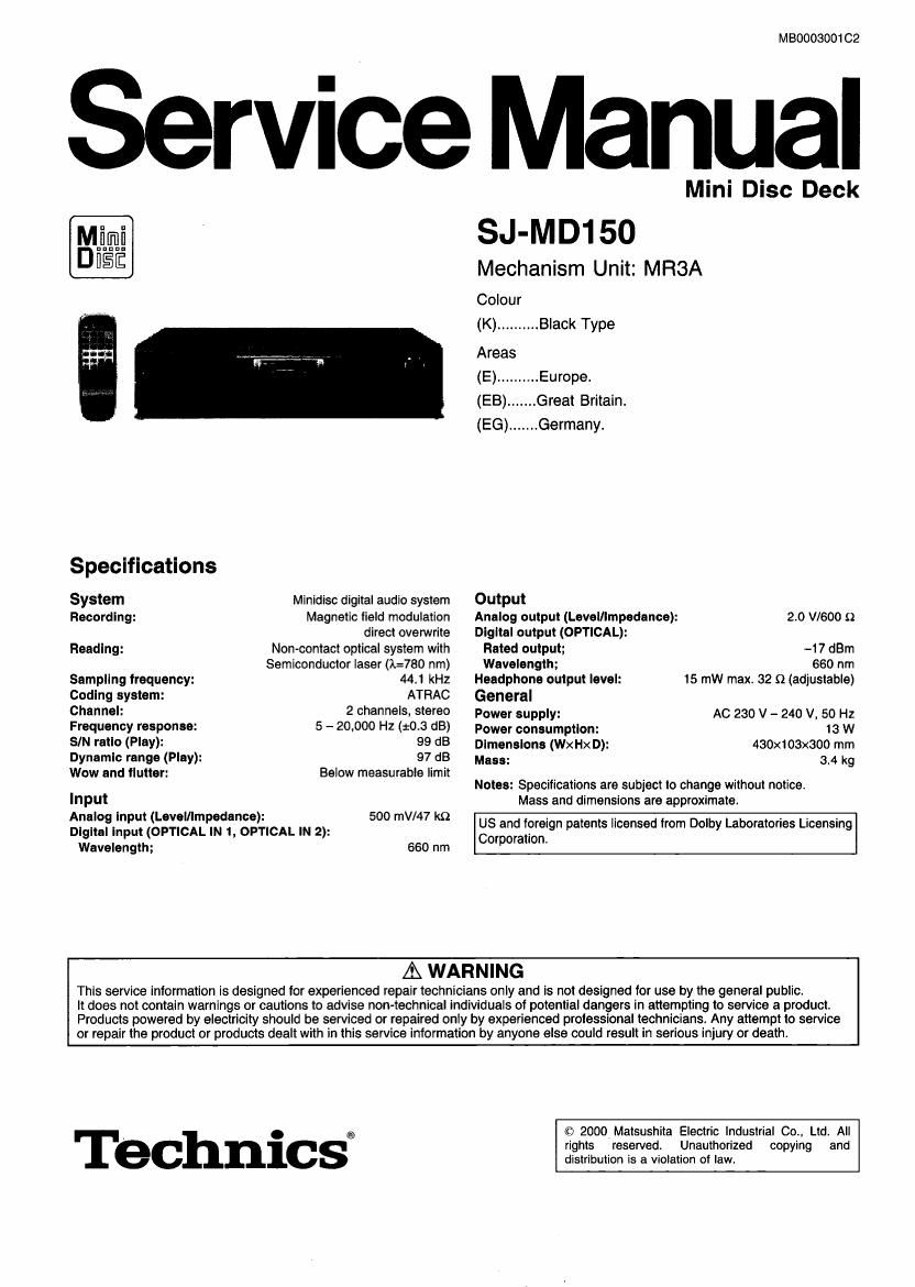
Technics SJMD 150 Service Manual

This is the 63 pages manual for Technics SJMD 150 Service Manual.
Read or download the pdf for free. If you want to contribute, please mail your pdfs to info@audioservicemanuals.com.

Page: 1 / 63
left right
Technics SJMD 150 Service Manual

Extracted text from Technics SJMD 150 Service Manual (Ocr-read)


Page 1

MBOOOBOO1 CZ

Service Manual

Mini Disc Deck
SJ-MD150

Mechanism Unit: MRSA
Colour

(K) .......... Black Type

Areas

(E) .......... Europe.

(EB) ....... Great Britain.
(EG) ....... Germany.

Specifications
System Minidisc digital audio system Output
Recording: Magnetic lield modulation Analog output (Level/Impedance): 2.0 V1600 9
direct overwrite Dlgltal output (OPTICAL):

Heading: Non-contact optical system with Rated output: -17 dBm

Semiconductor laser 0:780 nm) Wavelength; 660 nm
Sampling frequency: 44.1 kHz Headphone output level: 15 mw max. 32 (1 (adjustable)
Coding system: ATRAC General
Channel: 2 channels, SW60 Power supply: AC 230 V - 240 V. 50 Hz
Frequency response: 5 - 20,000 Hz (:03 as) power consumption: 13 W
SIN ratlo (Play): 99 dB Dimensions (Wx Hx D): 430x103x300 mm
Dynamic range (Play): 97 dB Mass: 34 kg
Wow and flutter: Below measurable limit . _

Notes: Specifications are subtect to change without notice.
Input Mass and dimensions are approximate.
Analog Input (Laval/Impedance): 500 mV/47 k9 . . . . .
Dlgltal Input (OPTICAL IN 1 OPTICAL IN 2): g8 and foreign patents licensed from Dolby Laboratories Licensing
orporation.
Wavelength; 660 nm
A WARNING

This service information is designed for experienced repair technicians only and is not designed for use by the general public.

It does not contain warnings or cautions to advise non-technical individuals of potential dangers in attempting to service a product.
Products powered by electricity should be serviced or repaired only by experienced prolessional technicians. Any attempt to service
or repair the product or products dealt with in this service information by anyone else could result in serious injury or death.

Technicsi

© 2000Matsushita Electric industrial Co.. Ltd. All
rights reserved. Unauthorized copying and
distribution is a violation of law.

Page 2

CONTENTS
Page

1 Accessorles ---------------------------------------------------------------------------- 2

2 Handllng Precautions for MD Unlt ----------

2.1. Handling of MD Unit (optical pickup)--
2.2. Grounding for electrostatic breakdown prevention
3 Precautlon of Laser Diode ------------------------------------------------------ 4
4 Caution for AC Mains Lead
5 Location of Controls -------

6 Self-Diagnostic Function -------------------------------------------------------- 7
6.1. Setting to the self-diagnostic function rrrrrrrrrrrrrrrrrrrrrrrrrrrrr 7
6.2. Canceling the selfvdiagnostic function
6.3. Clearing the sell-diagnostic function
7 Self Check Function --------------------------------------------------------------- 8
7.1. Setting to the self check function ------------------------------------ 8
7.2. Checking the operation buttons
73. Checking the FL display ----------
8 Operation Checks and Component Replacement Proceduress
8.1. Checking for the main P.C.B. -------------------------------- we
8.2. Checking for the FL PCB. and operation (1) P.C.B. ----- 10
8.3. Removal of the FL P.C.B., operation (1) P.C.B., operation
(2) P.C.B. and sensor P.C.B. ---------------------------------------- 10
8.4. Removal of the power switch P.C.B
8.5. Checking for the MD servo P.C.B. --
8.6. Replacement for the magnetic head and optical pickup~ 13
8.7. Replacement for the belt and loading motor ------------------ 15
3.8. Replacement for the traverse motor ------------------------------ 16

1 Accessories

- AC power supply cord for (E). (EG) areas
(RJA0043-1C) ...................

- AC power supply cord for (EB) area
(RJA0044-C) .............................. 1 pc.

- Optical-fiber cable
(RJLt xooeBos) ..........

Page

9 Schematic Diagram Notes ---------------------------------------------------- 17

10 Sohematic Diagram ................

11 Printed Circuit Board Diagram--
12 Type Illustration of ICs, Transistors and Diode
13 erlng Connection Diagram -------------------------------------------------- 37

14 Block Diagram -----------
15 Troubleshooting Guide-
16 Terminal Function of le-

16.1. |C1 (AN8772FHQ): RF Amp ----------------------------------------- 50

16.2. |C2 (AN8814SB-E1): Focus/Tracking Coil,
Spindle/Traverse Motor Drive ---------------------------------------- 50

16.3. ICS (MN66616RA4): ATRAC Encoder/Decoder, Servo
Signal Processor ---------------------------------------------------------- 50

16.4. |C10 (MN101D03DAA1): System Comm
165. lC72 (M51V4400D7FS): 4M DRAM -------
16.6. |0901 (M30218MAA102): System Control/FL Display~---52
17 Measurements and Adjustments

17.1. Necessary instruments

17.2. Set to the unit to adjustment mod
17.3. Laser power adjustment ----------------------------------------------- 54
18 Replacement Parts List
19 Cabinet Parts Locatlon-
20 MD Mechanism Unit Parts Location-
21 Packaging ----------------------------------------------------------------------------- 63

- Stereo phone cables
(RJL2P004BOBA)..

- Remote control transmitter
(EUR645272)..

- Batteries
(R6. AA, UM-3) .......................... 2 pcs.

Note: There are available on sales route.

Page 51

Pin Terminal I/O Function Pin Terminal I/O Function
No. Name No Name
25 F6 | FG input 98 AVDDO I Power supply terminal
26 NRECT 0 Rec/Play switchiqu signal output 99 AVSSO - GND terminal
27 IVDD2 I Power supply terminal for IIO pad 100 TEFSEL - Not used, open
28 None - Power supply terminal for IIO pad
:3 3X01; - GNDterm-nai 16.4. mm (MN101D03DAA1):
I | DRAM address output (Not used, open) System Control
32 FIADlO
33 HADS Pin Terminal I/O Function
| l O DRAM address output No Name
42 RADO 1 DAC RST O DAC reset signal output (L: reset)
43 RDT3 , 2 DEC 0 DE emphasis signal output
I | I/O DRAM data input/output (L: DE emphasis)
46 RDTO _ 8 MUTE - Muting signal output (Not used, open)
47 NRAS 0 DRAM row address strobe Signal output 4 AD RST O AD reset signal output (L: reset)
48 NCAS O 21:93: column address strobe Signal 5 NRF STBV 0 RF amp standby control signal output
49 NWE o DRAM write enable signal output 6 PC 0 PM" 39"pr C°""°' pm
50 NRST I Reset signal input 7 MSP HST 0 Reset Signal °".
51 SELAD I MSP/MDA, l/F address select signal input 8 LOAD1 O L°adfng m°t°r We 1 pm
. . 9 LOADO 0 Loading motor drive 0 output
52 SSCK | MSP/MDA, I/F clock Signal input ,
53 SSDW I MSP/MDA, I IF write data input 10 NEFMON 0 Magnetic head current output
54 sson o MSP/MDA, IIF read data output 11 TEST ' Tes e'm'ra' (lioi fed We")
t 12 TV SW | Rest detect sztch Signal input
55 MDISY 0 Leader synchronous signal output , . , _ .
56 SCTSY O ADIP synchronous noise output 13 DISC IN I Dlso ln detect switch signal input
57 SGSYNC 0 Frame synchronous signal output 14 REFLECT l Reflect detect swnch signal input
58 UV 1 | Power su | terminal 15 LOADSWO | Load OPEN detect switch signal input
on DP Y . (OPEN)
59 00 ' P°W°' SUPP! mm? '0 0 Pad 16 LOADSW1 | Load TRG detect switch signal input
60 DVSS1 - GND terminal (TRG)
61 F5384 0 384 F3 output 17 LOADSW2( l Load PLAY/REC detect swltch signal input
62 SCL 0 Bit clock signal output PLAY/REC)
63 SW8 0 Word clock signal output 18 LOADSWS I Load PLAY detect switch signal input
64 SDAP 0 Audio data signal output (PLAY)
65 SDAR I Audio data signal input 19 PROTECT | PROTECT detect switch signal input
66 LRCK | CD word clock signal input 20 MMOD - Not used. connected to GND
67 BCK i CD bit clock signal input 21 HST I RSSG signal input
53 DATA | CD data signal' input 22 UNITIEST - Test signal input (Not used, open)
69 TX 0 Digital audio inlenaoe signal output 23 082 - Test signal input (Nai used. open)
70 FtX1 I Digital audio interface signal 1 input 24 SCTSY i ADIP synchronous noise input
71 nxz | Digital audio interface signal 2 input 25 MDISY | Header synchronous noise input
72 EREFM . Not used, open 26 PANEL I Panel I/F request signal input-
73 REFM O EFM modulation signal output HEQ .
74 MONI3 _ Monitor 519" output (Not used, open) 27 LED OUT1 0 Drive signal output for LED drive (H: ON)
75 MONI2 - Monitor signal output (Not used, open) 25 LED om? i
76 MONIl - Monitor signal output (Not used, open) 29 LED OUTS
77 MONIO - Monitor signal output (Not used, open) 30 TEST ' Test terminal (Nd used, open)
78 T83 - Reserved (Not used, connected to GND) 31 Vii-22) ' P°Wei SUPP'Y termini
79 T32 - Reserved (Not used, connected to GND) 52 0301 I Crystal osmllator (E1002 MHZ)
80 T81 - Reserved (Not used, connected to GND) 33 0502 0
81 T80 Reserved (Not used, connected to GND) 34 V55 ' GND terminal
82 EXSYSCK External system clock input 35 XI ' Not used, connected 0 GND
(Not used, connected to GND) 36 X0 - N°i Used. 0P6
83 DVDDZ I Power supply terminal 37 V35 - GND terminal
84 XI l Crystal oscillator (i=16.9s44 MHz) 38 TESTOS - Test terminal (Not used, open)
85 x0 0 39 EEPCS - EEPROM chip select signal output
86 VDS 2 - GND terminal (0' sedr We")
57 RFDAT 0 RF serial data output 4° EEPCK fifisx cgziknfigna' °|°"
3: [Egg 3 a: :22: Eggkozgézf' 41 EEPDATA - EEPROM data signal input/output .
. _ (Not used, connected to GND Via reelstor)
90 TRCRS I Track cross Signal input 42 TEST04 - Test terminal (Not used, open)
9 OFT ' 0mm 5'9 "9" 43 TEST05 - Test terminal (Not used, open)
92 APCD 0 Laser power PWM,°'p 44 CF SYNC I MDA synchronous signal input
93 EXEFMCK ' 3:23;? $035313: resistor) 45 TESTOG - Test terminal (Not used, open)
94 PEFM1 0 EFM loop filter output 46 TEST07 I Connected to rec/play switch signal
95 EEMIREF | EFM PLL reference current input 47 TOK OK ' Tes' emma' (5 59¢ We")
96 EEMPLLF O EFM signal output 48 HF ON 0 HF module ON Signal output
97 PEFMS | EFM signal input

51