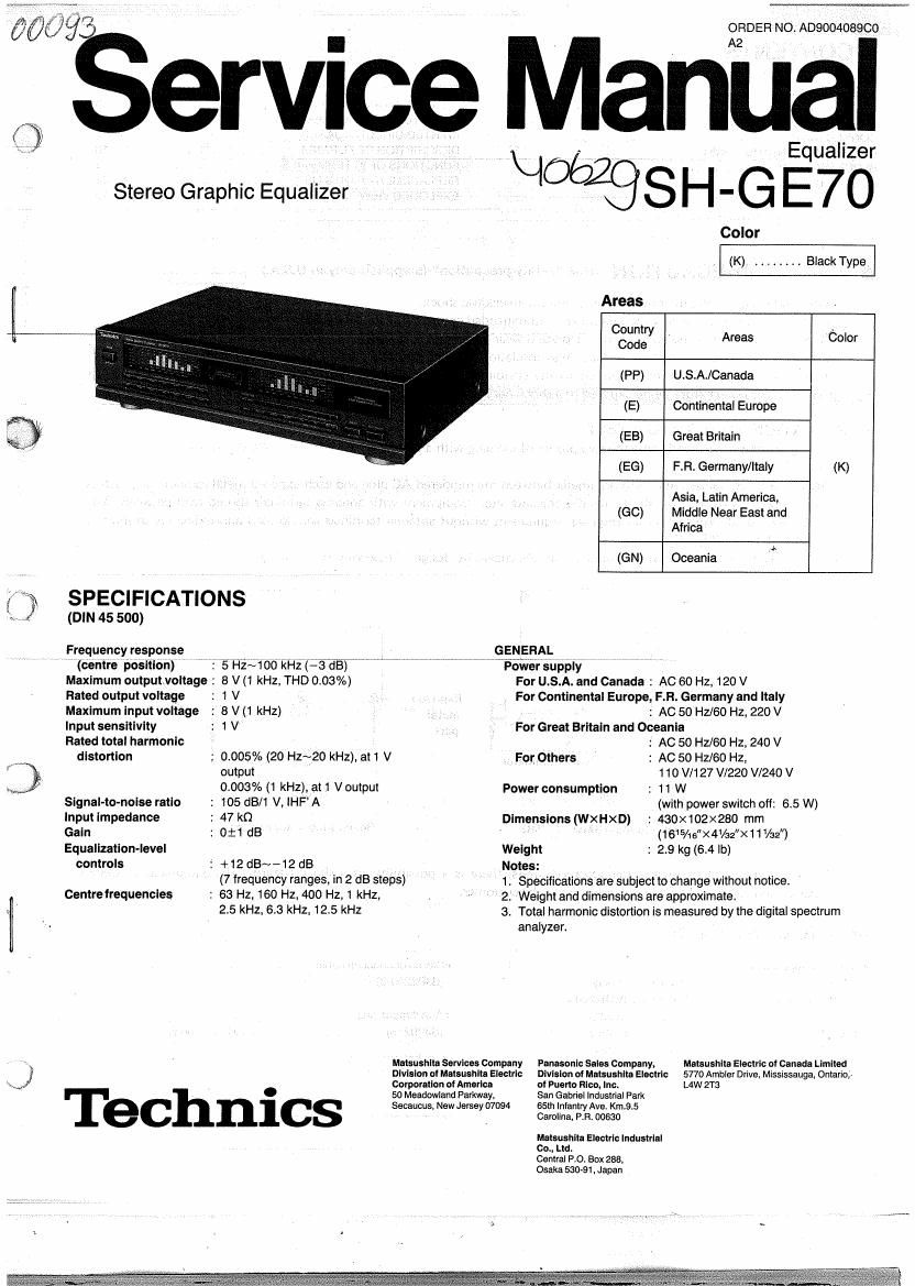
Technics SHGE 70 Service Manual

This is the 14 pages manual for Technics SHGE 70 Service Manual.
Read or download the pdf for free. If you want to contribute, please mail your pdfs to info@audioservicemanuals.com.

Page: 1 / 14
left right
Technics SHGE 70 Service Manual

Extracted text from Technics SHGE 70 Service Manual (Ocr-read)


Page 1

ervice Ma

Stereo Graphic Equalizer

e (um 45 500)

Frequency response
(centre position) '

Maximum outputtvoltage :

Rated output voltage

Maximum input voltage

input sensitivity

Rated total harmonic
distortion

Signal-to-nolse ratio

input impedance

Gain

Equalization-level
controls

Centre frequencies

Z ? SPECIFICATIONS

: 5 HZJIOO kHz (-3 dB)

8 V (1 kHz, THD 003%)

:1V
:8V(1kHz)
:1V

0005% (20 H2720 kHz), ail V
output
0.003% (1 kHz), at 1 Voutput

: 105dB/1V,IHF'A
: 47 k0
: 0:1 dB

: +12dB~~12 dB

(7 frequency ranges, in 2 68 steps)

: 63 Hz, 160 Hz, 400 H2,1 kHz,

25 kHz, 6.3 kHz, 125 kHz

ORDER NO. Aoeoo4089co

. A2 ; I
\I . , Equalizer
Color
(K) . . BIackType
Areas
03:32), Areas Color

(PP) USA/Canada

(E) Continental Europe

(EB) Great Britain

(EG) FR Germany/Italy (K)

Asia, Latin America,
(GO) Middle Near East and
Africa

(GN) Oceania

GENERAL
W VISEvIr-ér supply
For USA. and Canada : AC 60 Hz, 120 V
For Continental Europe, F.FI. Germany and Italy
: AC 50 HZ/60 Hz, 220 V
' For Great Britain and Oceania
: AC 50 Hfl60 Hz, 240 V

ForOthers : AC 50 H2160 Hi,
110 W127 V/220 V/240 V
Power consumption : t 1 W

(with power switch off: 6.5 W)
I 430x102><280 mm
(1615/16"X4/32"X i 1 V32")
: 23 kg (64 lb)

Dimensions (WXHXD)

Welg ht

Notes: { ,

1 . Specifications are subject to change without notice.

2 Weight and dimensions are approximate.

3. Total harmonic distortion is measured by the digital spectrum
analyzer

Matsushita SOWIGCS Company Panasonic Sails Company, Matsushita Eiectrlc of Canada LImIIed
Division at Matsushita Electric Division of Matauahlta Electric 5770 Ambler Drive, Mississauga. Ontario.»
Corporation of America at Puerto Rico, Inc. L4W 2T3
50 Meadowland Parkway, San Gabriel Indusllial Park
Seceucus. New Jersey 07094 65th lniantry Ave. Km,9.5

Carolina, PH. 00630

J _
Techn . CS

Mats-unit- Eieclric Industrial

60., Ltd.

Central PO. Box 238,

Osaka 53031, Japan

Page 2

TRANSISTORSA DIODES
IRING CONNEC ON DIAGRAM
PRINTED CIRCUIT BOARDS

DESCRIPTION OF FL PANEL . .1 "18
FUNCTIONS OF IC TERMINALS 19
, REPLACEMENT PA TV

'EXPLODED VIEW

DCthef 'S recomme

Note: Q Some exposedwparts may beisolated from the Chassis by design. These will read infinity.

4

I ACCESSORIES

. MeaSUre the

0. Replace IT W86!

urn on the power»


all exposed parts. (Fig. Bl: I

Antenna
terminal \

(Fig, Bl

Resistance = Approx 00

OAC power supply cord . . . .............................. 1 OStereo connection cable ................................. 2
(SJAi 75) ..... L ......... . For [PP] area only. (SJ P2249-3)
(SFDACO5E03) ......... . For [E] and [EG] areas.
(SJAI 93) ..... For [EB] area only. OAttachment plug ......................................... 1
(FIJAOOO4) . For [GO] area only. (SJP9215) .................. For [GC] area only

(SJA173) . .

. For [GN] area only.


I LOCATION OF CONTROLS

deuterium-mmm

Equalizer level-COntrol buttons

Power switch (power 1 off I on)

Power- -through" function
Discs. radio broadcasts, eIC. can be heard even It the
power of this unit is switched OFF. _
Note. however. that the power plug should be left
connected to the AC outlet.

(equalizer level Control)

These buttons are used for adjustment of the equalization

level of the left channel and right channel simultaneously.

Upper row: These buttons are. used to increase the level of
each sound range (frequency range).

These buttons are used to seléc 'e quIalization-level
display mode and any of the three types of Spectrum display
mode described below. '

l Equalization-level display mode
E0 level: Select this mode when you want to display the
equalization level. i"

' I Spectrum display modes

(spectrum analyzer)

bar: Select this mode when you want a bar-type
display.

dot: Select this mode when you want a dot-type
display

Lower row: these buttons are used to reduce the IeveI or

each sound range, (frequency range).

Memory mode-select button (memo mode)

This button is used to select the equalization memory mode to
be used.

manual: Select this mode to program a, desired curve to

the unit 5 memory or to retrieve a curve that you
have programmed.

fixed: Select this mode to retrieve a curve that was

originally pre-programmedto the units memory.

E] Memory buttonk(memory)h L,

This button Is used to program the equalization curve into the
memory. . ,

[E Equalization mode-select button (EQ on/off)
'This button is used to switch the equalization Correction

function E0 on and off". Each time a button Is pressed. the
mode changes alternately to one or the other of the following
modes

' E0 on: Select this mode to make an equalization correo

tion.

' EQ' off: Select this mode if no equalization correction is

desired.
Note that the E0 on" mode is automatically selected if a
preset-memory button or an equalizer level-control button is
pressed while this button is set to the fEO oft" mode.

Reverse button (reverse)
This button is used to reverse the equalization curve shown in
the display,

Select this mode when you want the peak to
be held in the display.

peak hold:

Preset-memory buttons (m-El)

These buttons are used to program an equalization curve into
the memory. or to retrieve a curve originally programmed into
the units memory.

Recording, mode selector
(EQ rec 1 off a on)

on: Set to this position to make a tape recordingol the

source while controlling the frequency response.
OH: Set to this position to record without equalizer correc-
tIon

Input selctor (1 source a tape)

Source: Set to this position to listen to the radio or a
compact disc. etc,

tape: Set to this position to listen to a tape deck
connected to the back of this unit.