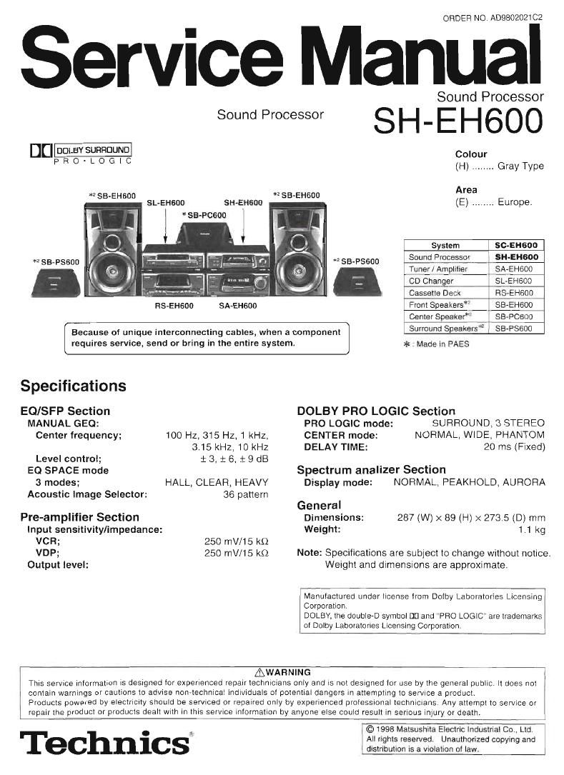
Technics SHEH 600 Service Manual

This is the 14 pages manual for Technics SHEH 600 Service Manual.
Read or download the pdf for free. If you want to contribute, please mail your pdfs to info@audioservicemanuals.com.

Page: 1 / 14
left right
Technics SHEH 600 Service Manual

Extracted text from Technics SHEH 600 Service Manual (Ocr-read)


Page 1

ORDER NO ADSBOZOZl C2

Service Manual

Sound Processor

Sound Processor S H _ E H 600

DU DOLBY sunnnuup Colour

PRO'LOGIC (H) ........ GrayType

*2 se-EHsoo *2 sa-EHeoo Area
SL-EHsoo SH-EHsoo (E) ....... Europe.
i *sa-Pcsoo

System i SC-EHBUO
*2 SB-PSGOO *2 SB-PSSOO Sound Prfiessor SH-EHGOO
Tune-HAI'EDIIIISI . SA-EHGOO

co Chang_er ' S_LEH600

, _ Cassette Deck _ RS-EH600

RS-EHBOO SA~EH600 Front Speakers*' _ SB-Efieoo
CenterSpeaker: 7 SBVPCSOD

Surround Speakels'zy SB-PSSOO

requires service, send or bring in the entire system. * : Made in PAES

Because of unique interconnecting cables, when a component

Specrfications
EQ/SFP Section DOLBY PRO LOGIC Section
MANUAL GEO: PRO LOGIC mode: SURROUND, 8 STEREO
Center frequency; 100 Hz, 315 Hz, 1 kHz. CENTER mode: NORMAL, WIDE, PHANTOM
3.15 kHz, 10 kHz DELAY TIME: 20 ms (Fixed)
Level control; i 3. t 6, t 9 dB
EQ SPACE mode Spectrum analizer Section
3 modes; HALL, CLEAR, HEAVY Display mode: NORMAL, PEAKHOLD, AURORA
Acoustic Image Selector: 36 pattern
General
Pre-amplifier Section Dimensions: 287 (W) x 89 (H) x 273.5 (D) mm
Input sensitivity/impedance: Weight: 1.1 kg
VCR; 250 mV/15 k0
VDP; 250 mV/15 k0 Note: Specifications are subject to change without notice.
Output level: Weight and dimensions are approximate

Manufactured under license irorn Dolby Laboratories Licensing
Corporation.

DOLBY, the doubie-D symbol DD and PRO LOGIC are trademarks
of Dolby Laboratories Licensing Corporation.

AWARNING
This service information is designed for experienced repair technicians only and is not deSIQned for use by the general public it does not
i contain warnings or cautions to advise non~technicai individuals ol potential dangers in attempting to serVice a product.
Products powered by electricity should be serviced or repaired only by experienced professmnal technicrans. Any attempt to service or
repair the product or products dealt with in this service information by anyone else could result in serious injury or death.

Tm

. < All rights reserved. Unauthorized copying and
ec nlcs distribution is a Violation of law.

Page 2

SH-EHSOO

I Contents

Location of Controls ..........................

Type Illustration 0! IC's, Transistors and Diodes .

Operation Checks and Wiring Connection Diagram ............................

Main Component Replacement Procedures.
To Supply Power Source ........................................
To check signals
Schematic Diagram
Printed Circuit Board Diagram

NOTE:

Refer to the service manual for Model No. SA-EHGOO for information on Accessories", Connections", Installation" ,

. 3, 4 Terminal Function of lCs
Block Diagram ................
Replacement Pans List ..
6 ~ 8 Cabinet Parts Location ..

Operations" and Packaging"t

I Location of Controls

$4 A) J

® E0 SPACE onltlat button (E0 SPACE ON/FLAT)

® Display mode select/demonstration button (DISP MODEI-DEMO)
© Display

@ DOLBY PRO LOGIC indicators (SURROUND, 3 STEREO, NORMAL, WIDE, PHANTOM)
© Multi control buttons (MULTI CONTROL, b, A, 4, V )
Acoustic image E0 button (ACOUSTIC IMAGE E0)

® E0 SPACE preset/manual select button (PRESETIMANUAL)
DOLBY PRO LOGIC on/ofl button (DOLBY PRO LOGIC, OFF/ON)
@ DOLBY PRO LOGIC mode select button (MODE)

@ DOLBY PRO LOGIC test signal button (TEST)

® DOLBY PRO LOGIC center mode button (CENTER MODE)

Page 5

l SH-EH600

I To Supply Power Source

This unit SH-EHGDD is designed to operate on power supplied from
the system connected. (For system connection, refer to Fig.1)

Fig. 1
When you have to test and service the unit SH»EH600 alone, use the following method
to supply power source and operate the unit:
DC Power Supply
1. Short the section between J124 and D101.
2. Short the section J306, .1307, J805 and .1302 with each other, (Point fl ) L
3. Short the section between J126 and 17 pin of the connector JK101, (Point B )
4. Short the section between J125 and .1101. (Point ) ONO O O
5. Apply +5 V DC power to the section between J12B and (+) foil side 010104, 9 g g g
6. Connect the DC power supply as shown below.

0 +12 V terminal ol the DC Power Supply connect to Point. .
OGND terminal ol the DC Power Supply connect to Point fl . Point [3
0-12 V terminal at the DC Power Supply connect to Point E .

Point m <-

Point C <-

DC Power Supply

JKtOl-tTpin

I To Check Signals

Input the audio signal and confirm in to be outputted from the terminal,

lNPUT OUTPUT Am
DI

Rh AU 0 AUDIO D© 6W6]
IN OUT mo 9_ g

90 VCR VCR v'Sp Jucn i