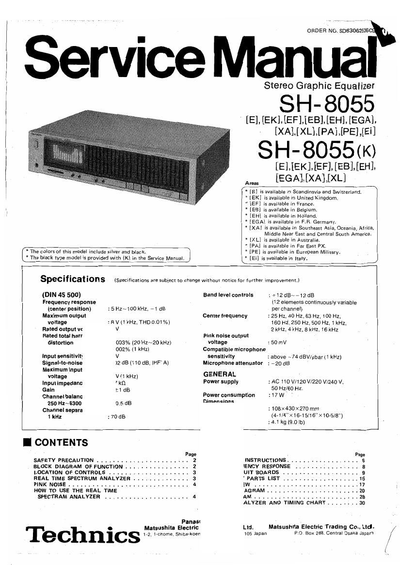
Technics SH 8055 Service Manual

This is the 31 pages manual for Technics SH 8055 Service Manual.
Read or download the pdf for free. If you want to contribute, please mail your pdfs to info@audioservicemanuals.com.

Page: 1 / 31
left right
Technics SH 8055 Service Manual

Extracted text from Technics SH 8055 Service Manual (Ocr-read)


Page 1

ORDER NO. 3033062526

Service Manual

CThe colors at this model include silver and black.

* The black type model is provided with (K) in the Service Manu

D

* [EH]

* [EGA] is available in F.R. Germany.

" [XA]

* [XL]

" [PA] is available in Far East PX.
* [PE] is available In European Military.
* [Ei] is available in Italy.

* [E] is available in Scandinavia and Switzerlam
* [EK] ' ' '
* [EF] is available in France.

* [EB] is available in Belgium

Stereo Graphic Equalizer

SH- 8055

[E] [EK] [EF] [EB] [EH], [EGA]

[XA] [XL] [PA], [PE], [Ei]

SH- 8055(K)

[E] ,,[EK] [EF] [EB] ,.[EH]
[EGA],[XA].[XL]

is available In United Kingdom,

is available in Holland.

is available in Southeast Asia, Oceania, Africa,
Middle Near East and Central South America.
is available in Australia.

Specifications

(DIN 45 500)
Frequency response
(center position)

Maximum output

voltage :EV(1 kHz, THD 0.01%)
Rated output vc V
Rated total harr

distortion 003% (20 Hz~20 kHz)

002% (1 kHz)
input sensitivity v
Slgnal-to-noise
Maximum Input

:5 Hz~100 kHz. -1 dB

)2dB(110dB, IHF'A]

voltage V (1 kHz)
Input impedanc ' k0
Gain E1 (13
Channel balonc
250 H1~6300 0.5 dB
Channel separa
1 kHz :70 dB
]
I CONTENTS

SAFETY PR ECAUTION .................

BLOCK DIAGRAM OF FUNCTION .....
LOCATION OF CONTROLS .........
REAL TIME SPECTRUM ANALYZER .

PINKNorse.....................'...

HOW TO USE THE REAL TIME
SPECTRAM ANALYZER

Page

bwwNN

Fanasi

Matsushita Electric

Te Chnics 172, rename, Shioa-koen

(Specifications are subject to change without notice for further improvement.)

Band level controls

Center frequency

Pink noise output
voltage

Compatible microphone

sensitivity
Microphone attenuator

GENERAL
Power supply

Power consumption

nimpneinnq

7

:+12dB~-12dB
(12 elements continuously variable
per channel)
:25 Hz, 40 Hz, 63 Hz, 100 Hz,
160 HZ', 250 Hz, 500 Hz, 1 kHz,
2 kH214 kHz, 8 kHz, 16 kHz

:50 mV

: above ~74 dBV/pbar (1 kHz)
: - 20 dB

: AC 110 V/120 V1220 V/24Cl V,
50 Hz{60 Hz.
: 17 W '

:108X430x270 mm
(4-1/4><16-15/16"><10-5/8")

:4.1 kg (90lb5

Page

INSTRUCTIONS .................. 6

ENCY RESPONSE . 8

UIT BOARDS ............. 5

' PARTS LIST . . . 15

' 17

. 20

. . . 28

ALYZER AND TIMING CHART ........ 30
Lid. Matsushita Electric Trading 00., Ltd.
105 Japan P.O Box 263. Central Osaka Japan

Page 2

I SAFETY PRECAUTIONS

memme

INSULATION RESISTANCE TEST

. Before servicing, unplug the power cord to prevent an electric shock,

. When replacing parts, use only manufacturers recommended components for safety

, Check the condition of the power cord. Replace if wear or damage is evident

. After servicing, be sure to restore the lead dress, insulation barriers, insulation papers, shields, etc.

. Before returning the serviced equipment to the customer, be sure to make the following insulation resistance test to
prevent the customer from being exposed to a shock hazard.

l. Unplug the power cord andshort the two prongs of'the plug with a jumper wire.

2.
3.

Turn on the power switch.

Measure the resistance value with ohmmeter between thejumpered AC plug and each exposed metal cabinet part, such as

screwheads antenna, control shafts, handle brackets, etc. Equipment with antenna terminals should read between SM!)

and 5.2MQ to all exposed parts.
, all exposed parts, (Fig. B)
Note:

Antenna
terminal

Exposed
metal
part

Ohmmeter

(Fig.A)

Resistance = 3M9-52 MQ

(Fig, A) Equipment without antenna terminals should read approximately infinity to

Some exposed parts may be isoiated from the chassis by design These will read infinity,

Exposed /-(

metal
part

0h mmeter

(Fig. 3)
Resistance = Approx 00

4, if the measurement is outside the specified limits, there is a possibility of a shock hazard. The equipment should be

repaired and rechecked before it is returned to the customer,

I BLOCK DIAGRAM OF FUNCTION

E-eriwlay mode)
0

Pin k noise generator

For detail, refer to Block Diagram on page 28.

L
Line input

source on (pink noise)
tape1
Tape deck 1 "playback" 0-0

off
Tape deck 2 "playback" GEL?

(rec mode) 0

Tape deck 1 "Rec out 0-.-OOEQ

Tape deck 2 Rec out" 0-

Line output

(display made) i
l

straigh t

R

Equalizer

:l

(mic attenuator)
-20dB OdB


Mic jack switch

-E mic
I _____________ _/

full range

FL

(display
level)