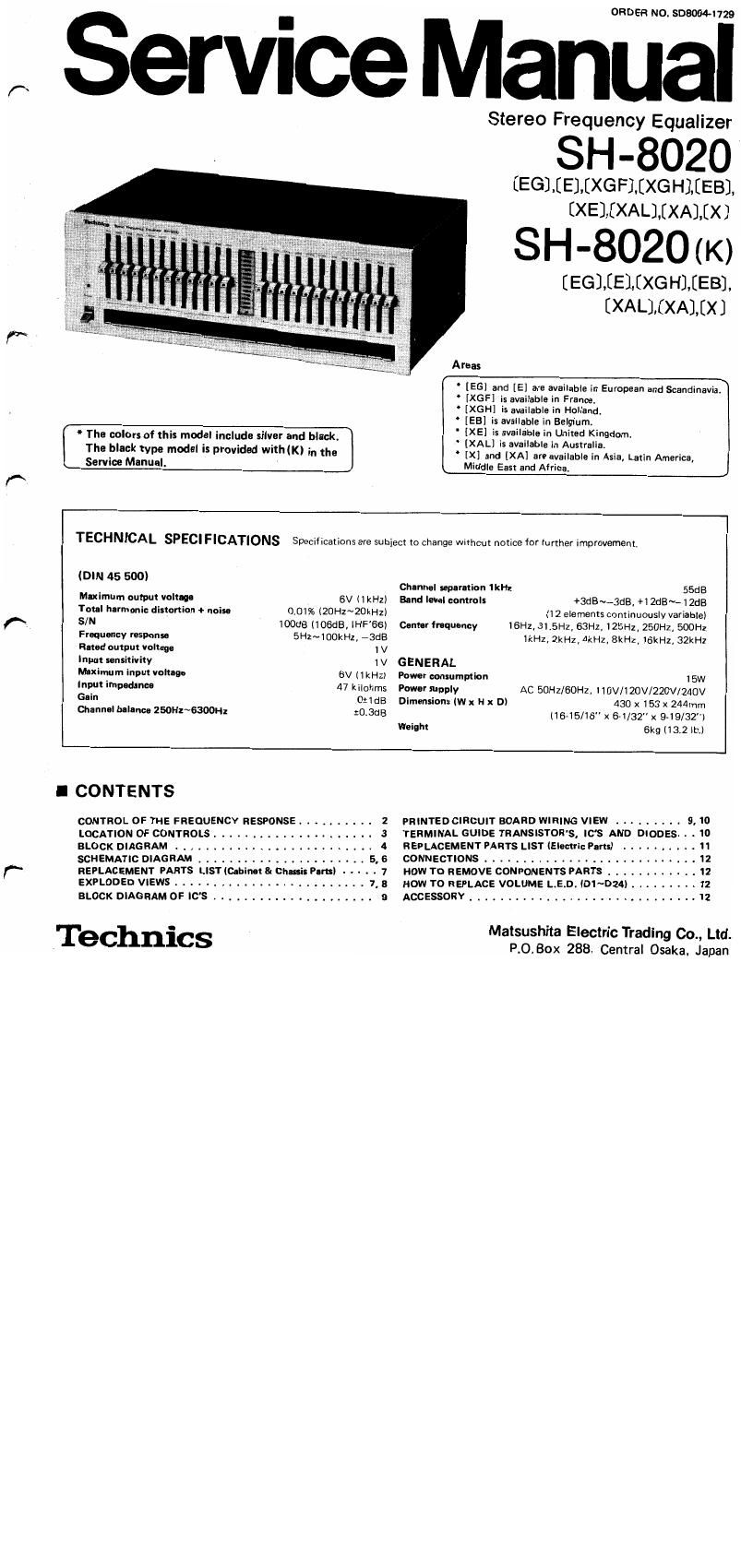
Technics SH 8020 Service Manual

This is the 12 pages manual for Technics SH 8020 Service Manual.
Read or download the pdf for free. If you want to contribute, please mail your pdfs to info@audioservicemanuals.com.

Page: 1 / 12
left right
Technics SH 8020 Service Manual

Extracted text from Technics SH 8020 Service Manual (Ocr-read)


Page 1

ORDER NO. 503004-1729

,x Servnce Manual

Stereo Frequency Equalizer

SH-8020

[EGJIEMXGFMXGHlEEB].

[XElEXALlEXAJIX]
S H - 802 0 ( K)
[EGLEELEXG H].EEB],
EXALlEXAlEX]
Areas

[EG] and [E] are available in European and Scandinavia.
[XGF] is available in France.
' [XGH] is available in Holland.
' [EB] is available in Belgium.
r 4' The colors of this model include silver and black. - SEEMS12:32:13:32:13:21110.
The black type "10(19' '5 [3'0de WMNK) in the [X] and [XA] are available in Asia, Latin America,
Service Manual. Middle East and Africa.
TECHNICAL SPECIFICATIONS Specifications are subject to change without notice for further improvement.
(DIN 45 500) Channel sap-ration IkHz SSdB
Maximum output voltage 6V (lkHz) End level controls +3dB~~3dB, +12dB~--12dB
Total harmonic distortion + noise 0.01% l20Hz~20kHzl (12 elements cominuwslv variable)
(N, SIN ioodB (IOSdB, lHF'BS) Oentlrfrnquoncy 16Hz, 31.5Hz, 63Hz, 125Hz,250Hz, 500Hz
Fraquancy msuonsa 5Hz~100kHz, -3dB lkHz, ZkHz 4kHz, BkHz, 16kH2,32kHz
fined nutput voltage I V
Input sensitivity 1 V GENERAL
Maximum input voltage 6V llkHz) Power consumption 15w
Input imuadance 47 kilohms Power supply AC 50Hz/6OH2, 110V/120V/220V/240V
Gain OtldB Dimensions (W x H x D) 430 x 153 x 244mm
Channel blllnco 2wH2~6300H2 30.3618 (1645/16" x 64/32" x 949/32")
Weighr 6kg (132 lb.)
I CONTENTS
CONTROL OF THE FREQUENCV RESPONSE ....... . . . 2 PRINTED CIRCUIT BOARD WIRING VIEW ........ . 9, 10
LOCATION OF CONTROLS ..... , ..... . 3 TERMINAL GUIDE TRANSISTOR'S, ICS AND DIODES. . . 10
BLOCK DIAGRAM . . . . . . . . 4 REPLACEMENT PARTS LIST (EIemric Parts) , . - - . . . . 11
SCHEMATIC DIAGRAM ..... . . ........ . . . . . 5, 6 CONNECTIONS ................ . . ...... . 12
f REPLACEMENT PARTS LISTlCabinat& Chmit Pans) - - - - - 7 HOW TO REMOVE COMPONENTS PARTS . . . . . 12
EXPLODED VIEWS ....... . ................. 7. 8 HOW TO REPLACE VOLUME L.E.D. (D1~D24) . . . 12
BLOCK DIAGRAM 0F ICS . . . . . . 9 ACCESSORY . . . ...................... I . 12

o _ Matsushita Electric Trading Co., Ltd.
.Technlcs

P.O.Box 288 Central Osaka, Japan

Page 2

SH-BOZOIK

TECHNISCHE DATE" »Spezifikationen kiinnen infolge Von Vorbess'erungen ohne Ankiindigung oeandert werden.

(DIN 45 500) q
Moximllauwnnuupannuno 6V( 1 kHz) Froquonzgangmlor +3dB-3dB, +12dB~-12dB
Gosamtklirrkktor + Rouse-hon 0,01% (20Hz~20kHz) (12 Regler, stufenios verstellbarl
Rauschahstlnd 100 dB Mimnfrcquonzon 16Hz, 31 .5Hz, 63Hz, 125Hz, 250Hz, 500Hz
Floqumzwng t 5Hz~100kHz, -3dB lkHz, 2kHz, 4kHz, BkHz,16kHz, 32kHz
Nonnau nnu 1 V

Einaamflm M 1v ALLGEMEINE DATEN

Moximaloinoanguponnum 6Vl1 kHz) Loistunguufnahmo 15W
Einnnnusimpodlnz 47 kilohms S'NMWONOW'IM Wechselstrom 50H2160H2.
Vortflrkunn 0:1dB l 10V/120V/220V/240V
Kan-lsy mmatria 250Hz~6300Hz 20,3dB Alumna-man (B x H x T) 430 x 153 x 244mm

Kanaltrannuno in 55dB Gowicht . 6kg

DONNEES TECHNIQUES Suiet a changement sans préaris.

(DIN 45 500)

Tension do sortie maxi GVllkHzl Commandos do nivaau do gamma +3dB a -3dB, +1213 9 -12dB

Dinonion harmonious tot-lo + bruit 0.01%(20H2~20kHzi _ (12 elements, continuellement variables)
Sigrid/bruit 100 as mamas emu-ram 16Hz. 31.5Hz, 63Hz, 125Hz, 250Hz, soon: fl
Combo do reponu SH: 3 100kHz a -3dB 1kHz, 2kHz, 4kHz, 8kHz,16kHz, 32kHz _ v
Tension do sortie nominal. 1 V
Sonsibilm d'untru 1 v G EN E RAITITES
~ Tension dontrbc maximal. 6Vl1 kHz) Cor-commotion 15W
Impadmoa d'ontroe 47 kilohms Alimontation CA 50Hz/60Hz, 110V/120V/220V/240V
Gain Oslda Dimensions (L x h x prlmm 430 x 153 x 224 mm
Equilibrm dc canal 250Hr~6300Hz 10.3dB (16-15/16 x 64/32" X 9-19/32")
Sip-rnion do canal (Hz 55dB Pdd 6kg ii 51.2le

I CONTROL OF THE FREQUENCY RESPONSE

o Band-level controls

These controls can be used to continuously vary the level of

each frequency response from +12 dB to -12 dB (or +3 dB to 7 3';

--3 dB). -- , :

With the frequency response flat at the "0" position: _

fit when the characteristics selector is set to the "normal - -
(all position, the frequency response will have a
peak if the controls are moved toward the "+" position,
and will reach a maximum peak of +12 dB at the "+12" '
position when the variable»range selector is set to the Band-level
"112 dB" l-al) position, and will reach a maximum ,m
peak of +3 dB at the +3 position when the variable-range
selector is set to the 13 dB (la-l position.

5 When the characteristics selector is set to the normal"
(-41) position, the frequency response will have a dip"
if the controls are moved toward the - position, and will
reach a maximum dip of -12 dB at the "v12 position
when the variable-range selector is set to the 112 dB
(-->ll position, and will reach a maximum dip of -3 dB 5
at the -3 position when the variableArange selector is set
to the 13 dB" (la-l position. However, if the charav
cteristics selector is set to the "reverse" (la-l position,
the polarity of the frequency-response level is the opposite
of that shown by the variable-range indicators.

The figure shows the changes in the frequency response when

the bandvlevel controls are used. Each of the 12 left and 12

level

Odo-rumour 1: are:

iroquoncy (normalized)

0 Total frequency response

Response (

_ , 16 31.5 63 125 250 500 ill 2k 4k 8k 16k 32k
right controls can be used to vary the frequency response With Frequency (Hz) -

the same characteristic curve.

Page 9

sH-aozo/K

I CONNECTIONS

. is 3i.) flu - meats
gm Egg
SH-8020 .
Tapedeck

l HOW TO REMOVE CONPONENTS PARTS

0 How to remove the front panel

1) Pull out the frequency level adjusting knobs (24 pcs).

2) Remove the setscrews on both sides of the cabinet.
(56-4 pcs in Development on page 7, 8.)

3) Remove the cabinet.
(Shift the cabinet slightly backwards, then remove it
upwards.)

4) Remove the front panel setscrews. (55-1 pc, 61-2 pcs-
front side of set, 69-3 pee in Development on page 7, 8.)

5) Remove the front panel.

6) Detach the connector (Cl-pin).

0 How to remove the pilot lamp base plate

1) Remove the front panel. (Refer to "How to remove the
front panel".)

2) Detach the connector (7-pin).

3) Disengage the latch (10-1 pc in Development on page
7, 8) of pilot lamp base plate (PLl ~6) and then remove
the base plate.

4) Remove the setscrew (53-1 pc in Development on page
7, 8) of pilot lamp base, plate (PL7, 8) of the front
panel to remove the base plate.

I ACCESSORY

A1 (SJP2129-5)

I HOW TO REPLACE VOLUME
L. E. D. (D1~D24)

1. Pull out the volume control knob and also remove the LED
by using pliers.

2. Connect the LED in correct polarity (negative on top and
positive on bottom side). Evenwhen one LED is in wrong
polarity, all LED will not light up.

LED Short sidee Top side
--.
, . Bottom side
Long side® Volume

Note: Because of series connection, even when only one LED '
is defective, all LED will not light up.

0 How to remove the volume control base plate
1) Remove the front panel. (Refer to How to remove the
front panel".)
> 2) Remove the volume control cover setscrews.
in Development on page 7, 8.)
(Remove the 4 claws on top of the volume control cover
by using a screwdriver.)

(68-4 pcs

3) Remove the volume control base plate setscrews. (57-8 A
pee in Development on page 7, 8.) RA}
4) Detach the connectors (9-pin 4 pcs).

A2 (SJP5213-1)

Accessory of A2 is available in Asia,
Latin America, Middle East and Africa.

Printed in Japan
80047800®A.M .