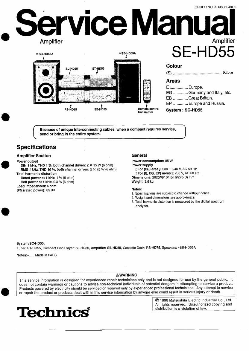
Technics SEHD 55 Service Manual

This is the 29 pages manual for Technics SEHD 55 Service Manual.
Read or download the pdf for free. If you want to contribute, please mail your pdfs to info@audioservicemanuals.com.

Page: 1 / 29
left right
Technics SEHD 55 Service Manual

Extracted text from Technics SEHD 55 Service Manual (Ocr-read)


Page 1

.

ORDER NO, AD9803049C2

Service Manual

Amplifier

* SB-HD55A

SL-HD55 ST-HD55

f
RS-HD75

=l: SB-HDSSA

Amplifier
Colour
(S) .......................................... Silver
Areas
E Europe.
EG. Germany and Italy, etc.
EB ............. Great Britain.
EP ............. Europe and Russia.

RBII'IDIE control
transmitter

System : SC-H D55

Because of unique interconnecting cables, when a compact requires service, J

[ send or bring in the entire system.

Specifications

Amplifier Section
Power output
DIN 1 kHz, THD 1 %, both channel driven: 2 X 15 W (6 ohm)
RMS 1 kHz, THD 10 %, both channel driven: 2 X 25 W (6 ohm)
Total harmonic distortion
Rated power at 1 kHz: 1 % (6 ohm)
Half power at 1 kHz: 0.3 % (6 ohm)
Load impedanced: 6 ohm
SIN (rated power): 85 dB

System/SC-HD55:

General

Power consumption: 85 W
Power supply
[ For (EB) area ]: 230-- 240 V, AC 50 Hz
1 For (E, EG, EP) areas]: 230 v, AC 50 Hz
Dimensions: 202(W)1104.5(H)/273(D) mm
Weight: 3.6 kg

Notes:

1. Specifications are subject to change without notice.

2. Weight and dimensions are approximate.

3. Total harmonic distortion is measured by the digital spectrum
analyzer.

Tuner: ST-HD55, Compact Disc Player: SL-HD55, Amplifier: SE-HDSS, Cassette Deck: RSvHD75, Speakers: *SB-HDSSA

Notes:*...... Made in PAES

AWARNING
This service information is designed for experienced repair technicians only and is not designed for use by the general public. it
does not contain warnings or cautions to advise non«technica| individuals of potential dangers in attempting to service a product.
Products powered by electricity should be serviced or repaired only by experienced professional technicians. Any attempt to service
or repair the product or products dealt with in this service information by anyone else could result in serious injury or death.

Technic§

© 1998 Matsushita Electric Industrial 00., Ltd.
All rights reserved. Unauthorized copying and
distribution is a violation of law.

Page 2

SE-HD55 7 |

I Contents

Page

Page

Accessories 2 Power Source ONIOFF and Signal Check ................................... 12
Before Repair and Adjustment . 2 Blue LED . .
Caution for AC Main Lea . 3 Type Illustration of le, Transistors and Diodes
Protection Circuitry . . 4 Schematic Diagram .
Location of Controls .. . 4 Printed Circuit Board Diagram .
Installation 4 Block Diagram .....
Convenient Functions . 5 Wiring Connection Diagram .
Connections ............. . 6, 7 Replacement Parts Lis
Operation Checks and Cabinet Parts Location

Main Component Replacement Procedures ................... 8 ~ 10 Packaging

I Accessories

0 AC power supply cord ............. 1 pc.
For (EB) area: For (E, E6, EP) area:
(VJA0733)

(RJA0019-2K)
7 (ix ,

0 Remote control batteries 2 pcs.
[(RB/L'Fts (AA, UM-3)]
Note: These are available on sales route.

@

0 FM indoor antenna ..
(RSA0007)

.. 1 pc.

0 Remote control transmitter ....... 1 pc.

(aune4s4e7)

0 AM loop antenna set (RSA0021)

AM loop antenna ...................... 1 pct
Antenna holder with stand ....... 1 pc.

0 Speaker cords ........................ 2 pcs.
(REE0393)

Antenna holder without stand ...... 1 pc.
Screw .......................................... 1 pc.

(fl;@fiiv

0 Antenna plug adaptor
For (EB) area only:
(SJ P9009)

I Before Repair and Adjustment

(1) Turn off the power supply. Using a 10 Q, 10 W resistor, connect both ends of power supply capacitors (C715~718) in order to

discharge thevoltage.

(2) Before turning the power supply on, after completion of repair, slowly apply the primary voltage by using a power supply voltage
controller tomake sure that the consumed current at 50/60 Hz in NO SIGNAL mode should be shown below with respect to

supply voltage 230 V/240 V.
Area (E) (55} (5") (EB)
Power supply voltage AC 230 V AC 240 V
Consumed current 50 Hz 50 Hz 60 ~ 180 mA 50 Hz 55 ~ 175 mA

Page 12

SE-HD557 77

I Blue LED

IThe LED mounted to each side of the front panel of this set is very sensitive to static electricity. When handling the LED base plate, be very careful
about it.

0 Do not replace a blue LED singly. If replaced singly, it may be subject to electrostatic breakdown or deterioration in quality.
When replacing the LED base plate, be sure to replace L and R sides simultaneously to permit the brightness adjustment.

* For configuration at the time of supply of replacement parts, refer to the PCB Diagram (on Page 17).

I Schematic Diagram

Page
M AC IN TERMINAL CIRCUIT ............................... .......................... 13~15
E] OPERATION CIRCUIT ............................................................................................ . ...... . ........... 13

MAIN CIRCUIT
E] RELAY CIRCUIT .
E POWER TRANSFORMER CIRCUIT .. .
LED (R) CIRCUIT .............................................. . ............................................................ . ........... 14
LED (L) CIRCUIT .............................. ..... . ............. . ............ 14

14, 15


C This schematic diagram may be modified at any time with the development of new technology.

Notes:

08301 :Power STANDBY 0 ION switch (POWER. STANDBY O ION)
08302 : Source input select control switch (INPUT SELECTOR UP)

0 8303 : Source input select control switch (INPUT SELECTOR DOWN)
0 $304 : Bass control switch (BASS UP)

0 $305 : Bass control switch (BASS DOWN)

I 5306 :Treble control switch (T REBLE UP)

0 S307 :Treble control switch (T REBLE DOWN)

0 $308 : Bass, demo switch (BLFS/DEMO)

0 Indicated voltage values are the standard values for the unit measured by the DC electronic circuit tester (high-impedance) with the chassis
taken as standard. Therefore, there may exist some errors in the voltage values, depending on the internal impedance of the DC circuit tester.
No mark: Power ON

0 important safety notice:

Components identified by A mark have special characteristics important for safety,
Furthemore, special parts which have purposes of tire-retardant (resistors), high-quality sound (capacitors), low-noise (resistors), etc. are used.
When replacing any of components. be sure to use only manufacturers specified parts shown in the parts list.

0 Cautionl
l0 and LSI are sensitive to static electricity,
Secondary trouble can be prevented by taking care during repair.
Cover the parts boxes made of plastics with aluminum foil.
Ground the soldering iron.
Put a conductive mat on the work table.
Do not touch the legs of lC or LSI with the fingers directly.

0 Voltage and signal line
-D- : Positive voltage line
I..- : Negative voltage line

-> : Source signal line

_12_