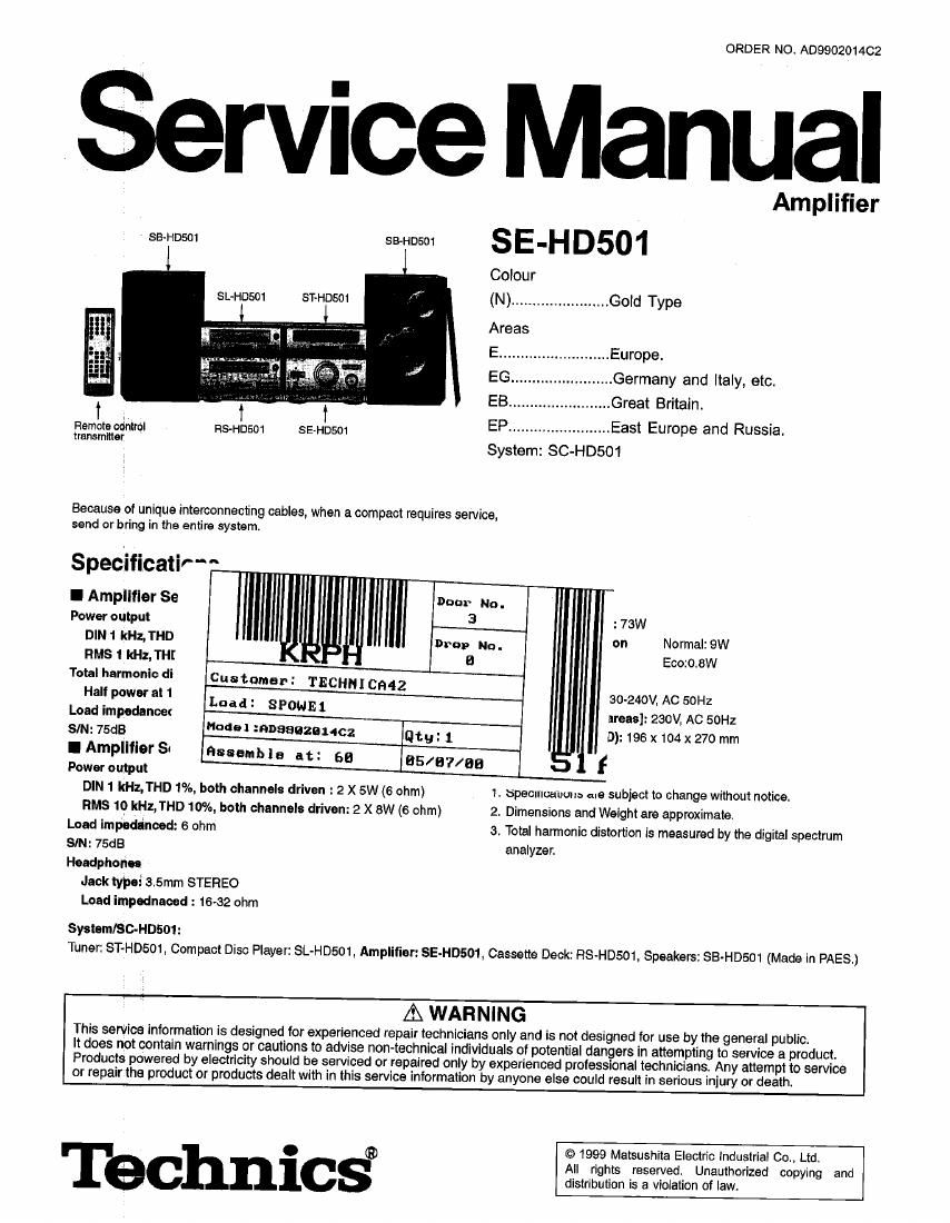
Technics SEHD 501 Service Manual

This is the 28 pages manual for Technics SEHD 501 Service Manual.
Read or download the pdf for free. If you want to contribute, please mail your pdfs to info@audioservicemanuals.com.

Page: 1 / 28
left right
Technics SEHD 501 Service Manual

Extracted text from Technics SEHD 501 Service Manual (Ocr-read)


Page 1

ORDER NO A0990201402

Service Manual

Amplifier
sB~HD§01 9501 S E 'H D501

Colour
SL-HDSOt swosm ., (N) ...................... Gold Type
Areas
E .......................... Europe.
EG... .................. Germany and Italy, etc.


EB. ..... Great Britain.
Ramas cam] RS~HD501 SEHDW EP.... ..... East Europe and Russia.
mm System: SC-HD501

Because of unique interconnecting cables, when a compact requires service,
send orbring in the entire system.


Specification ,

l Amplifier Se

Power output : 73W
DlN1 kHz, THD J on Normal: 9W
nus 1 kHz, THE - Eco:0.8W

Total harmonic di customer: TECHNI C942

Half power at 1
I. :
Load impedance: Dad SPOHE 1

SIM: 75dB Model :noaaazaucz thy: 1
l Amplifier Si Essen!) 1 a at: 55 [35/97/38 f
Power output

DIN 1 kHz,THD 1%, both channels driven : 2 X5W (6 ohm) 1. specmoauuns are subject to change without notice.

RMS 10 kHz,THD 10%, both channels driven: 2 X 8W (6 ohm) 2. Dimensions and Weight are approximate,
Load impedenoed: 6 ohm 3, Total harmonic distortion is measured by the digital spectrum
SIN: 75dB analyzer.
Headphones

Jaoktypei 3.5mm STEREO

Load impednaoecl : 16-32 ohm

System/SGHDSM:
Tuner: ST-HD501, Compact Disc Player: SL-HDSO1,Amplitiar:SE-HD§01, Cassette Deck: RS-HDsO1, Speakers: SB-HD501 (Made in PAESJ

30-240V, AC 50H:
areas]: 230V, AC 50H:
D): 196 x104 x 270 mm

A WARNING

This service information is designed for experienced repair technicians only and is not designed for use by the general public.

It does not contain warnings or cautions to advise non-technical individuals at potential dangers in attempting to service a product.
Products powered by electricity should be serviced or repaired only by experienced professional technicians. Any attempt to service
or repair the product or products dealt with in this service information by anyone else could result in serious injury or death.

. (5) © 1999 Matsushita Electric industrial Co., Ltd.
All rights reserved. Unauthorized copying and
distribution is a violation of law.

Page 2

CONTENTS

1 Accessories --------------------------------------------------
2 Before Repair and Adjustmen
3 Caution for A0 Main Lead ------

4 Operating Instructions ............................................................... 4
5 Operation Checks and Component Replacement Proceduress
6 Power Source ONIOFF and Signal Check ------------------------------ 12
1 Schematic Diagram Notes ......................................... 12

7.1. Type Illustration of IC's, Transistors and Diodes- 12

1 Accessories

Page
7.2. Schematic Diagram Notes ---------------------------------------------- 13
8 Schematic Diagram ------------------------------------------------------------------ 14

9 Printed Circuit Board Diagram-
10 Block Diagram -----


11 Wiring Connection Diagram-
12 Replacement Parts List-
13 Cabinet Parts Location --
14 Packaging -------------------

-AC power supply cord ...,.........1 pc. - Remote control transmitter ...... 1pc. - Speaker cords 4 pcs.
For (EB) area: For (E, EG, EP) areas: (RAK-HDA07WH) (HEE0499) (REE0853)
(FlJA0053-2X) (FlJA0019-X)

1% 7 . I .
we, .
r 1
. Remote control batteries ........ 2 pcs. . AM loop antenna set (RSA0021)

[(RG/LFlG (AA, UM-3)]
Note: These are available on sales route.

6

AM loop antenna 1 pc.
Antenna holder with stand 1 pr:

Antenna holder ........................... 1 pc.
Screw .......................................... 1 pc.

goo

- FM indoor antenna ................... 1 pc. - Antenna plug adaptor ............... 1 pc.
(HSAOOO?) For (E B) area only:
(SJPQOOQ)

2 Before Repair and Adjustment

1.Turn off the power supply. Using a 100 , 10W resistor, connect both ends of power supply capacitors (0102-105, 127) in order

to discharge the voltage.

2. Before turning the power supply on, after completion of repair, slowly apply the primary voltage by using a power supply voltage
controller to make sure that the consumed current at 50/60 Hz in NO SIGNAL mode should be shown below with respect to

supply voltage 230 V/240 V.

Area (E) (EG) (EP) (EB)
Power supply voltage AC 230V AC 240V
Consumed current 50 Hz 50 Hz 60-180 mA 50 Hz 1 55475 mA

Page 3

3 Caution for AC Main Lead
(For United Kingdom)

(EBl area code model only)

For your safety, please read the following text careful-
ly.

This appliance is supplied with a moulded three pin
mains plug for your safety and convenience.

A 5-ampere fuse is fitted in this plug.

Should the fuse need to be replaced please ensure
that the replacement fuse has a rating of 5-ampere
and thatit is approved by ASTA or BSI to B81362.
Check for the ASTA mark @ or the BSI mark $ on
the body of the fuse.

lf theaplug contains a removable luse cover you must
ensure that it is refitted when the fuse is replaced.

If you lose the fuse cover the plug must not be used
until a replacement cover is obtained.

A replacement fuse cover can be purchased from
your local dealer.

CAUTION!

IF THE FITTED MOULDED PLUG IS UNSUIT-
ABLE FOR THE SOCKET OUTLET IN YOUR
HOME THEN THE FUSE SHOULD BE RE-
MOVED AND THE PLUG CUT OFF AND DIS-
POSED OF SAFELY.

THERE IS A DANGER OF SEVERE ELECTRI-
CAL SHOCK IF THE CUT OFF PLUG IS iN-
SERTED INTO ANY 13~AMPERE SOCKET.

If a new plug is to be fitted please observe the wiring
code as shown below.
if in any doubt please consult a qualified electrician,

IMPORTANT

The wires in this mains lead are coloured in accor-
dance with the following code:

Blue: Neutrai, Brown: Live.

As these colours may not correspond with the coloured
markings identifying the terminals in your plug, proceed
as follows:

The wire which is coloured Blue must be connected to
the terminal which is marked with the letter N or col-
oured Black or Blue.

The wire which is coloured Brown must be connected
to the terminal which is marked with the letter L or co-
loured Brown or Red.

WARNING: DO NOT CONNECT EITHER WIRE TO
THE EARTH TERMINAL WHICH IS MARKED WITH
THE LETTER E, BY THE EARTH SYMBOL J?- OFI CO-
LOUREDGREEN ORGREEN/YELLOW.

THIS PLUG IS NOT WATERPROOFéKEEP DRY.

Before use
Remove the connector cover.

How to replace the fuse

The location of the fuse differ according to the type of
AC mains plug (figures A and B). Confirm the AC
mains plug fitted and follow the instructions below.
Illustrations may differ from actual AC mains plug.

1. Open the fuse cover with a screwdriver.

2. Replace the fuse and close or attach the fuse cover.

Figure A

Figure B

I Fuse
(5 ampere)

Page 6

I Connections

Connect the AC mains lead after you have connected all other
cables.

To prepare the AM loop antenna wire and speaker cords, twist
the vlnyl cover tlp and pull all.

:nfi I$ :m
fa 1 Adhesive tape
was <8
I \
IIEEJ' 3


Connecmr

TO connect cables

White line


To unplug cables

Hold the conneclor lrom
both ends and pull it ouL

w

W}

To household
AC outlet


Red (+)
Black(-)

Red (+)

Blue (-) I
Black (7)

Page 17

9 Printed Circuit Board Diagram

17

A I B I C l E l
1
2
__ ToTUNEH
MAN 5.
3 4
4
5
6
L 203mm
REPZBIOAM)
- ELECTRICAL PARTS LOCATION (
__ i may. Lo. R51. Lo. Hei Lo. ReL Lo. Rev. Lo 554. La. Rel. L04 Her L5 Rel. Lo.
4N0. No No. No. N. No. No No. No. No. No. No. No. No No. No No.
fl POWER SUPPLV ROB.
mm 55 5104 2c [ms 45 0:25 50 R104 6C 5117 45 owe 55 0117 1c 0425 55
0102 55 D105 45 D116 AC RL101 5:: mos 45 5504 5:: 0107 50 mm 2c 0129 55
7 0103 4C D106 46 DH? 3C CN101 28 R106 SC R505 20 0108 GB C119 28 (2130 58
0104 so D107 so D118 25 CN102 55 H107 55 5505 20 c105 45 c120 35 5501 25
0105 10 D105 6:: D119 5c owns 55 man 55 mos 2c one so 0121 45
mm; 20 D109 50 5125 55 cmo4 ac R109 40 R709 20 C111 4c 0122 45
5501 25 0110 50 D123 55 owns ac mm 45 01m 4c 0112 55 0123 2C
@702 2c 5m 55 5124 55 arms 4:: R111 so am 5c cna 3:: 0124 ac
mm as 5112 55 D125 55 W713 55 R113 so 0103 6c cm 55 c125 55
__ D102 55 D113 4c 0126 55 mm 2c R114 10 0104 so 0115 5:: C125 35
0103 26 DITA AC D127 50 H102 SB M16 20 GIGS SC 0116 30 C127 SC
n SPEAKER TERMINAL 5,05.
(3502 35 was 35 051715 35 R528 45 5544 45 5557 so 0519 55 0534 55 c552 55
0505 3D D707 2F ON716 2E R529 3E R545 3D R559 4F 0520 2E C535 5D 0553 4D
0505 55 D705 3F W701 45 H530 55 5545 an 5550 45 0523 55 43535 55 C554 45
8 0509 SE L501 4F JK501 5E R531 3E R547 40 R702 2F (3524 SE (>545 2D C703 SF
0510 55 5502 45 JKGOZ so 5532 55 5545 45 R703 25 0525 55 0547 45 0704 SF
0511 25 L603 4:: 55m 45 5553 25 5549 an 5704 35 0525 55 5545 45 5705 25
@512 so L504 45 R525 45 5554 2D 5550 2D 0502 so 5531 4D (2549 45
0701 25 we: 35 5525 4F R535 25 5551 40 cm 45 0552 45 0550 45
5705 35 cum 55 5527 45 5545 4D 5552 45 0515 45 0553 50 0551 55