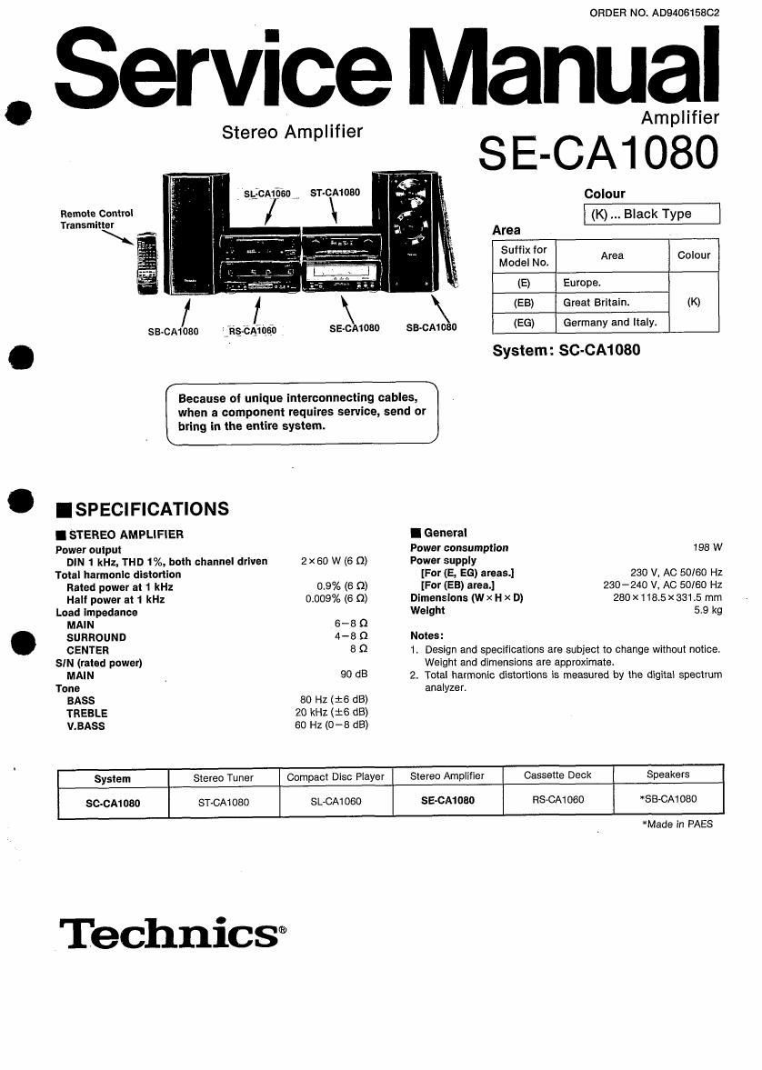
Technics SECA 1080 Service Manual

This is the 14 pages manual for Technics SECA 1080 Service Manual.
Read or download the pdf for free. If you want to contribute, please mail your pdfs to info@audioservicemanuals.com.

Page: 1 / 14
left right
Technics SECA 1080 Service Manual

Extracted text from Technics SECA 1080 Service Manual (Ocr-read)


Page 1

ORDER NO AD940615802

Service Manual

Stereo Amplifier

: 'sgcmfiso

Remote Control
Transmitter

sa-cmoso jog-ems}: 7

ST-CA1 080

SE-CA1 080

Amplifier

SE-CA1080

Because of unique interconnecting cables,
when a component requires service, send or
bring in the entire system.

ISPECIFICATIONS

I STEREO AMPLIFIER
Power output

Colour
(K) Black Type
Area
332:): Log Area Colour
(E) Europe.
(EB) Great Britain. (K)
SB-CA1080 (EG) Germany and Italy.
System: SC-CA1 080
I General
Power consumption 198 W

DIN 1 kHz, THD 1%, both channel driven 2 x60 W (6 0) Power supply
Total harmonic distortion [For (E, EG) areas.] 280 V, AC 50/60 Hz

Rated power at 1 kHz 0.9% (6 (I) [For (EB) area.] 230-240 V, AC 50/60 Hz

Half power at 1 kHz 0.009% (6 0) Dimensions (w x H x D) 280 x1185 x 331.5 mm
Load impedance Weight 5.9 kg

MAIN 6-8 0

SURROUND 4-8 Q Notes:

CENTER 8 Q 1. Design and specifications are subject to change without notice.
SIN (rated power) Weight and dimensions are approximate.

MAIN 90 d3 2. Total harmonic distortions is measured by the digital spectrum
Tone analyzer.

BASS 80 Hz(16 dB)

TREBLE 20 kHz (:6 dB)

V.BASS 60 HZ (0-8 dB)

System Stereo Tuner Compact Disc Player Stereo Amplifier Cassette Deck Speakers
SC-CA1080 ST-CA1 080 SL-GAI 060 SE-CM 080 RS-CAi 060 *SB-CA1080

TechniCS®

*Made In PAES

Page 2

SE-CA1 080

ICONTENTS

PROTECTION CIRCUITRY
BEFORE REPAIR AND ADJUSTMENT
LOCATION OF CONTROLS.
ACCESSORIES ..................
OPERATION CHECKS AND

COMPONENT REPLACEMENT PROCEDURE
REPLACEMENT OF THE FOOT .............................
POWER SOURCE ONIOFF OF THIS UNIT SE-CA1080
MESUREMENTS AND ADJUSTMENTS .........................

SCHEMATIC DIAGRAM .
BLOCK DIAGRAM ..........
PRINTED CIRCUIT BOARDS
WIRING CONNECTION DIAGRAM ..
CABINET PARTS LOCATION ..
REPLACEMENT PARTS LIST...
RESISTORS AND CAPACITORS ..
PACKAGING ...............................

Note: Refer to the Installation and Connections and Concerning the remote control and Quick referenc of remote
control operations of Service manual for Model No. ST-CA1080 (E, E6), Order No. AD9406153C2.

I PROTECTION CIRCUITRY

The protection circuitry may have operated if either of
the following conditions is noticed:

0 No sound is heard when the power is turned on.

0 Sound stops during a performance.

The function of this circuitry is to prevent circuitry
damage if, for example, the positive and negative
speaker connection wires are shorted", or if speaker
systems with an impedance less than the indicated
rated impedance of the amplifier are used.

If this occurs, follow the procedure outlines below:
t. Turn off the power.

2. Determine the cause of the problem and correct it.
3. Turn on the power once again after one minute.

Note:

When the protection circuitry functions, the unit will
not operate unless the power is first turned off and
then on again.

I BEFORE REPAIR AND ADJUSTMENT

Disconnect AC power, Discharge both Power Supply Capacitors C701 and C702 through a 109, SW resistor to ground.

DO NOT SHORT-CIRCUIT DIRECTLY (with a screwdrive blade, for instance), as this may distroy solid state devices. After
repairs are completed, restore power gradually using a variac, to avoid overcurrent.

Current consumption at 50 HzIGO Hz in N0 SIGNAL mode should be shown below with respect to supply voltage

230VI240VVI110-127Vl220-240V.

Power supply voltage AC 230V AC 240V
50Hz 110~250mA 50 Hz 1oo~240mA
I60H
0°"sumed current 50 z 60Hz 88~200mA 60Hz 80~192mA
ILOCATION OF CONTROLS
Stereo amplifier section
(D PowerSTANDBV tb/ON" - - \
switch .::l:l - ©°E:l©
(POWER, STANDBY (DION) °° [Zions -m
Press to switch the unit from on to _. _. [:1 I

standby mode or vice versa. In standby
mode, the unit is still consuming a small
amount of power.
® Standby indicator (STANDBY)

When the unit is connected to the AC
mains supply, this indicator lights up in
standby mode and goes out when the
unit is turned on.

© Headphones jack
@ Output power meters

© Dolby Pro-Logic center mode in-
dicators

Dolby Pro-Logic OFF/0N button
Dolby Pro-Logic center mode
select button

Delay time adjustment button

Test signal transmission button
8. EIASS control

BASS control

TREBLE control

©®9@© @@

u'ri'é'awéuut): o-u ====oou

\\ . M

W. U.

Page 4

SE-CA1 0810 l

I OPERATION CHECKS AND MAIN COMPONENT REPLACEMENT PROCEDURES

NOTE
1. This section describes procedures for checking the operation of the maior printed circuit
boards and replacing the main components.

2. For reassembly after operation checks or replacement, reverse the respective procedures.
Special reassembly procedures are described only when required.

. 3. Select items from the following index when checks or replacement are required.
4. Illustrated screws are equivalent to actual size.
5. Refer the parts No. on the page of Main component Replacement Procedures, if necessary.

oGontents
oohecking Procedure for each P.C.B. page.
1.CheckingfortheoperafionP.C_B_nu-n-uuuuu-uuu.n-n-o'u..-u...-uuuuuuu...-..uu.....--uuo4
2.Checkingfonhemamp.03..........................................................5

-Ivlain Component Replacement Procedures
1. Replacementforthe power IC and regulatortransistor-n-------- ------------- ----- ----------- 5

I Checking Procedure for each P.C.B.

1. Checking for the operation P.C.B.

Operation P.C.B.

6)»), 6 (Black)

[RH D30007]

@mm 43.3 (Black)
[XTBS3+8JFZ1)