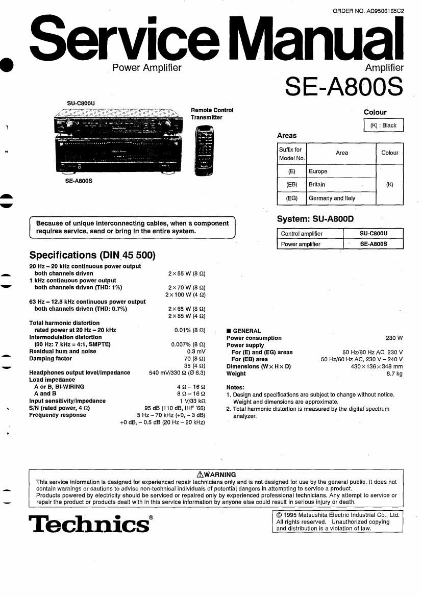
Technics SEA 800 S Service Manual

This is the 32 pages manual for Technics SEA 800 S Service Manual.
Read or download the pdf for free. If you want to contribute, please mail your pdfs to info@audioservicemanuals.com.

Page: 1 / 32
left right
Technics SEA 800 S Service Manual

Extracted text from Technics SEA 800 S Service Manual (Ocr-read)


Page 1

I l

i i

ORDER NO. AD950616502

Service Manual

_ Power Amplifier Amplifier
SU-CBOOU
Remote Control Colour
Transmitter
(K) : Black
Areas
Suffix for Area Colour
Model No.
(E) Europe
55AM (EB) Britain . (K)
(EG) Germany and Italy V
Because of unique interconnecting cables, when a component SYStem' SU-ABOOD
requires service. send or bring in the entire system. Comm, amplifier 51143300
Power amplifier se-Aaoos '
Specifications (DIN.45 500)
20 Hz -20 kHz continuous power output
both channels driven 2x 55 W (8 9i
1 kHz continuous power output
both channels drlven (THD: 1%) 2 x 70 W (8 S2)
2 x 100 w (4 52)
63 Hz - 12.5 kHz continuous power output '
both channels driven (THD: 0.7%) 2x 65 W (8 9)
2X 85 W (4 £2)
Total harmonic distortion
rated power at 20 Hz -20 kHz 0.01 % (8 Q) I GENERAL 7
lntermodulation distortion Power consumption 230 W
(50 Hz: 1 kHz = 4:1, SMPTE) 0.007% (8 9) power supply
Residual hum and noise 0.5 mV For (E) and (EG) areas 50 Hz/60 Hz AC, 230 v
Damping factor 70 (8 9) For (EB) area 50 Hz/GO Hz AC, 230 V- 240 V
35 (4 9) Dimensions (Wx Hx D) 430x 136x348 mm
Headphones output level/Impedance 540 mV/SSO 52 (0 6.8) Weight 8.7 kg
Load impedance .
A or B, Bl-Wll-thG 4 52 - 16 9 Notes:
A and B 8 9-16 52 1. Design and specifications are subject to change without notice.
Input SEHSiiViW/impedance 1 Was k9 Weight and dimensions are approximate.

SIN (rated power. 4 52)
Frequency response

95 dB (110 dB, [HF 66)
5 Hz -70 kHz (+0, - 3 dB)
+0 dB, - 0.5 dB (20 Hz - 20 kHz)

2. Total harmonic distortion is measured by the digital'speotrum
analyzer.

AWAHNING
This service information is designed for experienced repair technicians only and is not designed for use by the general public. it does not
contain warnings or cautions to advise non~technical individuals of potential dangers in attempting to service a product.
Products powered by electricity should be serviced or repaired only by experienced professional technicians. Any attempt to service or
repair the product or products dealt with in this service information by anyone else nonld result in serious injury or death.

Technics®

© 1995 Matsushita Electric Industrial Co. Ltd.
All rights reserved. Unauthorized copying
and distribution is a violation of law.

Page 2

jE-ABOOS

l Contents

Before Repair.
Protection Circuitry
, Accessories......,
Caution for AC Mains Lead.
Connecting the Audio Components .............
Connecting the Speakers and Power Supply.
Front Panel Controls
Listening to Sound
Recording ..........

Page Page
Operation Check and
2 Main Component Replacement Procedures
2 Schematic Diagram ............
3 Printed Circuit Board Diagram
4 Wiring Connection Diagram
5
S
B
9


. 10~1G
14~18
19~22

. 23

24

25~25

2930

Block Diagram ..........
Replacement Parts List
Cabinet Parts Location
Packaging ...........................................................


l Before Repair

(1) Turn off the power supply. Using a 10 9,10 W resistor, connect both ends of power supply capacitors (C701, C702) in order to
discharge the voltage.

(2) Before turning the power supply on, after completion of repair, slowly apply the primary voltage by using a power supply voltage
controller to make sure that the consumed current at 50 Hz In NO SIGNAL mode should be shown below with respect to supply
voltage 280 V/240 V.

Power supply voltage AC 230 V AC 240 V

Consumed current 50 Hz 100 ~ 200 mA 100 - 200 mA

l Protection Circuitry

The protection circuitry may have operated it either of the following conditions is noticed:

I No sound is heard when the power is switched ON.

0 Sound stops during a performance.

The function of this circuitry is to prevent circuitry damage if, for example, the positive and negative speaker connection wires are
shorted", or if speaker systems with an impedance less than the indicated rated impedance of this unit are used.

If this occurs, follow the procedure outlined below:

1. Switch OFF the power.

2. Determine the cause of the cause of the problem and correct it.

3. Switch ON the power once again.

Note:
When the protection circuitry functions, the unit will not operate unless the power is first switched OFF and then ON again.

I Accessories

5 AC power supply cord 0 Stereo connection cable
(E, E6) areas : (RJA0019-2K) .............. 1 (EB) area: (VJA0733) ........................... 1 (SJP2276) ...........

o Amplifier connection cable 0 Remote control transmitter 0 Batteries
inJLeoom 51 o) ............................. 1 (RAK-SU1 BOWH) ........................... 1 (UM-4. 'AAA', R03) ................................... 2
, Note: These are available on sales route.

6

Page 25

U

l Replacement Parts List

SE-Aaqos ,.

Notes: lmponent safety notice:
Components identified byA mark have special characteristics important for saletyc
Furthermore, special pans which have purposes of firsretaruant (resistors), high-quality sound (capacitars), lam-noise (resistors). are. are used.
When replacing any cl componenls. be sure to use only menulaciures specified pans shown in the pens list.
The parenthesized indications in The Remarks columns specify the areas. (Heler to the cover page lor area.)
Fame without these imitations can be used ior all areas,
Flemote Central Ass'y. Supply period for three years from termination of production.
*The (SF)" malk denotes the standard pan.
: indicates pans that are supplied by Video Recorder Division.
Ref. No. Part No. Part Name 8: Description Remarks Ref. No. Part No. Part Name 3: Description Remarks
D453 MAZQWA DIODE
INTEGRATED CIRCUIT (S) D501. 502 MATES DIODE
D503. 504 MA4160M DIODE A
10401 AN7062N IO, VOLTAGE AMP. 7 D505 MA105 DIODE
I050] SVI32050 IO, PORTER AMP. A 0505 13320 lTA DIODE
I0502 RSNBOOOA IO. V-AMP D501 MAIBS DIODE
10721 AN78L0 STA IO, REGULATOR 7 A D502 MA40ERL DIODE
10701 AN78L05TA IO, REGULATOR A 0603. 5'04 MAIBS . ' DIODE
10801, 802 UPD4027BO IO, J-K FLIP-FLOP D005 SLR'305VC LED
IOEOfI 0N3131R IC, OFTO-ISOLATOR 0701-704 P300DLF DIODE A
D706 MA 105 DIODE
TRANSISTORS) 0711- 714 ISR35200TB DIODE A
D721 MAIBS DIODE
0401, 402 ZSA1123RST'I'A TRANSISTOR 0731-742 SLR-305m LED
0451. 452 ZSCZOSIIETTA TRANSISTOR D752 MA4150M DIODE A
0453. 454 ZSOSEIIAIRIA TRANSISTOR D762 MAlbS DIODE I
0455. 455 ZSA130 DAIRTA TRANSISTOR D781 MA4150M DIODE A
0501-503 ZSAQ HZEFPTA TRANSISTOR D762 MAl 55 DIODE
0543 ZSA1309AIRTA TRANSISTOR D701- 794 ISRHSZOOTB DIODE A
0001 2503311 RTA TRANSISTOR D795, 708 MA4I4OM DIODE A
0502 ZSOIIRIIAIRTA TRANSISTOR 0797, 798 MATES DIODE
0603 2503040AOSTA TRANSISTOR D801 SLR-305W LED _
0504-605 ZSORIIllAI RTA TRANSISTOR 0803, 804 144165 DIODE
0511, 012 2303311AI RTA TRANSISTOR D800 MA155 DIODE
0701 ZSCSSIIAIRTA TRANSISTOR DBOQ- 812 M04165 _ DIODE
0781 2502374POAU TRANSISTOR A 0813, 814 MA4082MTA DIODE A
0791 ZSK33OGRYTA TRANSISTOR A 0815, 816 SLR-305W LED
07 92 ZSJIDSGRYTA TRANSISTOR A D821 MAIBT DIODE A
0793 2SC3940AOSTA TRANSISTOR A D822-824 MAIES DIODE
0704 25A1534RTA TRANSISTOR A
080L 802 UN4215 TRANSISTOR COIL (5)
0803-807 UN4111 TRANSISTOR
0808 2SA130 EAI RI'A TRANSISTOR L1 SLOZESOMI'MO COIL A
0809 2503311AI RTA TRANSISTOR L401, 402 ELEXTIOOKAR COIL
0310 UN4111 TRANSISTOR L403 BLOZRNIREZTZ COIL
0822, 823 UN4215 TRANSISTOR L501-504 SLQY18G-10 COIL
0324 ZSCEIIIIAI RTA TRANSISTOR L791-797 ELEXT 1ROKA9 COIL
0825 UN4111 TRANSISTOR
TRANSFORMER (S)
DIODE (S)
Tl RIPlPSROO fi-W POKER TRANSFORMER A
D401. 402 MA167 DIODE T701 RTP1J58001~W POWER TRANSFORMER A
D403, 404 MA4035MTA DIODE
D405. 405 MAlfiS DIODE FUSE (S)
D451 MA165 DIODE
D452 MA405OMTA DIODE E1 XBA2025TDO FUSE, 250V, 2. 5A A

-25-