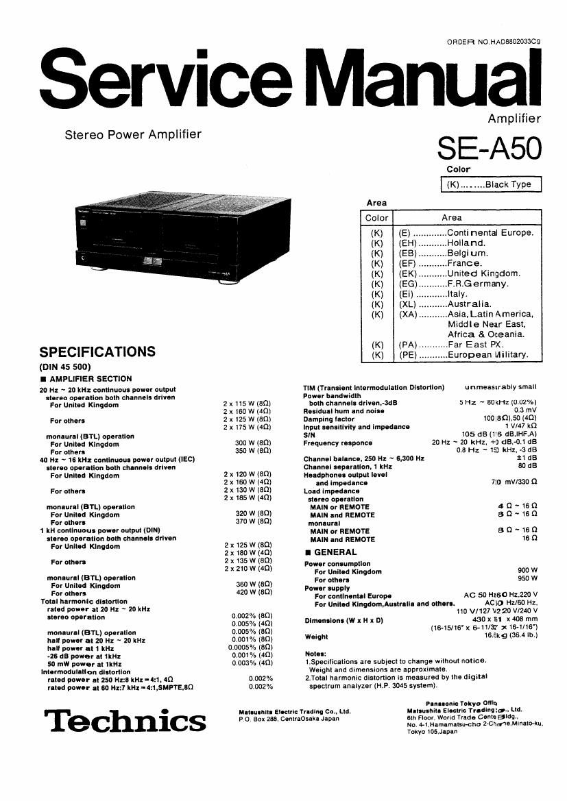
Technics SEA 50 Service Manual

This is the 20 pages manual for Technics SEA 50 Service Manual.
Read or download the pdf for free. If you want to contribute, please mail your pdfs to info@audioservicemanuals.com.

Page: 1 / 20
left right
Technics SEA 50 Service Manual

Extracted text from Technics SEA 50 Service Manual (Ocr-read)


Page 1

ORDE R NOMADBSOZOGSCQ

Service Manual

Stereo Power Amplifier

SPECIFICATIONS

(DIN 45 500)
I AMPLIFIER SECTION

20 Hz ~ 20 kHz continuous power output
stereo operation both channels driven
For United Kingdom

For other!

monaural (BTL) operation
For United Kingdom
For other:
40 it: ~ 16 kHz continuous power output (lEC)
Ilcreo operation both channels driven
For United Kingdom

For other!

monaural (BTL) operation
For United Kingdom
For other!
1 kH continuous power output (DIN)
stereo operation hoth chennele driven
For United Kingdom

For other!

monlurll (BTL) operation
For United Kingdom
For others
Total harmonic distortion
rated power at 20 Hz ~ 20 kHz
stereo operation

moneural (BTL) operation
hall power at 20 Hz ~ 20 kHz
hall power at 1 kHz
.25 on power at1kl-iz
50 mill power at 1kHz
Intermodulntlon distortion
rated power It 250 "2:9 kHz-4:1. 40
reted power at so Hz:7 kHz-4:1,5MPTE,BQ

Technics

2x115Wt80)
2x 160W (4n)
2x125W(80)
2x175W(4Q)

300 W (80)
350 W (80)

2 x 120 w (an)
2 x160 w (40)
2 x130 w (30)
2x 135w (4a)

320 W (80)
870 W (80)

2 x125 W (30)
2 x 180 W (40)
2 x 135 W (80)
2 x 210 W (49)

360 W (an)
420 W (8(2)

0.002% (30)
0.005% (40)
0.005% (80)
0.001 % (30)
0,0005% (80)
0.001% (40)
0.003% (40)

0.002%
0.002%

Meteunnlte Electric Trlolno Cot, Ltd.
PO. Box 288, CentraOsaka Japan

Amplifier

8 :-A50

Color

Area
Color Area
(K) (E) ,. Continental Europe.
(K) (EH) Holland.
(K) (EB) Belgium.
(K) (EF) .France.
(K) (EK)... .United Kingdom.
(K) (EG)... .F.R.Germany.
(K) (Ei) . .ltaly.
(K) (XL) .Australia.
(K) (XA) ........... Asia, Latin America,
Middle Near East.
Africa & Oceania.
(K) (PA) ........... Far East PX.
(K) (PE) ........... European Military.

TlM (Transient lntermodulatlon Distortion)
Power bandwidth
both channels driven,-3dB

u nmeasurably small

5 Hz ~ BUKHZ (002%)

Residual hum and noise 0.3 mV
Damping lactor 100130),50(4Q)
Input sensitivity and impedance 1 WW k0

SIN 105 (13(16 dB,lHF,A)
Frequency responce 20 Hz -' 20 kHz. +0 dE,-0.l GB

0.8 Hz ~ 13) kHz. ~13 :18
Channel balance. 250 H: ~ 6.300 It: :1 dB
Chennai separation. 1 kit: 80 dB
Headphone: output level

and Impedance 720 mV/330 (1
Load impedance
stereo operation
MAIN or REMOTE 4 (1 ~ 16 0
MAIN and REMOTE 8 Q ~ is Q
monlurll
MAIN or REMOTE B Q ~ 16 0
MAIN and REMOTE 16 Q
I GENERAL
Power consumption
For United Kingdom 900 w
For other: 950 W

Power supply
For continental Europe
For United Klngdom,AuetreIl-i and othere.

AC 50 H260 H2220 V
ACSO H1160 Hz.

110 V/127 V220 V/240 V
430 x In x 408 mm
(16-15/16' X 6-11/32 x 16-1/16)

Weight 16.8)(9 (36.4 lb.)

Dimeneione (W x H x D)

Not":

LSpecitlcations are subject to change without notice.
Weight and dimensions are approximate.

2.Total harmonic distortion is measured by the digital
spectrum analyzer (H.P. 3045 system),

Plnuonlo Tokyo Quin.
Mateo-nit- Electric delndcgn Ltd.
6th Floor, World Trade Canto Bldg,
No. 4-1,Hamamalsu-cho Emir-"GIMMBKHU,
Tokyo 105,.llpen

Page 2

m

I CONTENTS

BEFORE REPAIR AND ADJUSTMENT
PROTECTION CIRCUITRY
ACCESSORIES ..................
LOCATION OF CONTROLS
DISASSEMBLY INSTRUCTIONS
PRINTED CIRCUIT BOARDS
TERMINAL GUIDE 0F


SCHEMATIC DIAGRAM ............
WIRING CONNECTION DIAGRAM
BLAOCK DIAGRAM ..................
MEASUREMENTS AND ADJUSTMENTS
EXPLODED VIEW
REPLACEMENT PARTS LIST
RESISTORS AND CAPACITORS


TRANSISTORSDIODES AND ICS .................... 10

I BEFORE REPAIR AND ADJUSTMENT

(1) Turn oft the power supply. Using a 100, 10W resistor, shortcircuit both ends of power supply capacitors
(C609,Ct310)in order to discharge the voltage.
(2) Before turning on the power switch of the unit.
A, Connect the voltage controller to the primary side.
3. Connect the AC ampere meter to the primary side or connect the DC voltage meter to the 15" circuit
at the secondary side.
0. Turn the VR of lCQlVR401,VR402,VR551 and VR552)to minimum(counterclockwise).
D. After setting the output to zero of the voltage contoller,turn on the power switch of the unit.
And increase the output of voltage controller gradually.
Then, check carefully whether the current value of primary side become more than following value or
whether the DC voltage of secondary side is increasing slowly.
E. If the value of current is increasing unusually or the DC voltage is not increasingJower the output
level of voltage contoller immediately.
0 The current value of the primary side at no signal. (Contirm the power supply voltage of each area and provided

voltage of the unit.)

AC110V
400 ~ 850mA

AC127V
390 ~ 840mA

ACZZOV
200 ~ 450mA

A0240V
180 ~ 43DmA

Power supply voltage

Consumed current 50/60Hz

I PROTECTION CIRCUITRY

The protection circuitry of the amplifier may have
operated if either of the following conditions is noticed:

o No sound is heard when the power is turned on.

0 Sound stops during a performance.

The functlon of this circuitry is to prevent circuitry damage
if, for example. the positive and negative speaker
connection wires are shorted , or it speaker systems with
an impedance less than the indicated rated impedance

of the amplifier are used.

If this occurs. follow the procedure outlined below:
1.Turn off the power.

2.Determine the cause of the problem and correct it.
3.Turn on the power once again.

Note:

When the protection circuitry functions, the unit will not
operate unless the power is first turned off and then

on again.

- ACCESSORIES 5

0 Stereo connection cable .......................................................... 1

(SFDACOSE03)
for [E], [EG], [El], [EH]. [EB] and [EF] areas.

For United Kingdom and some areas,the power cord is
directly attached to the unit.
Configuration of AC power supply cord differs according to area.

-2-

Page 4

I DISASSEMBLY INSTRUCTIONS

PM; No. How to remove the cablnet Rekao. HOW to remove the front panel
Procedure oRemove the 8 screws (o~6). "10:? 1- Remove the 2 screws (0, 9) 80d emOVe

the bracket.

2. Remove the 6screws (eye).

3. Remove the front panel in the direction of the
arrow.

4. Pull out the 1 connector (J3).

5. Pull out the 2 flat cables (J4, J5).

Power switch
Knob

Power switch P. C .B.

Ret.2No. How to remove the Input terminal P.c.B.
Prolflure 1. Remove the 2 connectors (J1 , J2).
2. Remove the 2 screws (0, 9).
How to remove the flat cable
Pull out the flat cable while
pressing the connector \ Flat
cable
/
Ref. No. How to remove the power switch P.c.B and Comm),
3 LED P.c.B.
if? 1. Remove the power switch knob by pushing it Ret.5No. How to remove the front shield case
from behind the front panel.
2. Remove the 2 screws (0, 9). Procedure
3. Remove the power switch P.c.B. 1->4-.5 ; :emovet:efsc:e:s|[(10~e). d' .
4_ Release the 2 claws. . fegiovet e ron S ta case in the traction
5. Remove the LED P.c.B. ° e 0-
LE D R c.e.