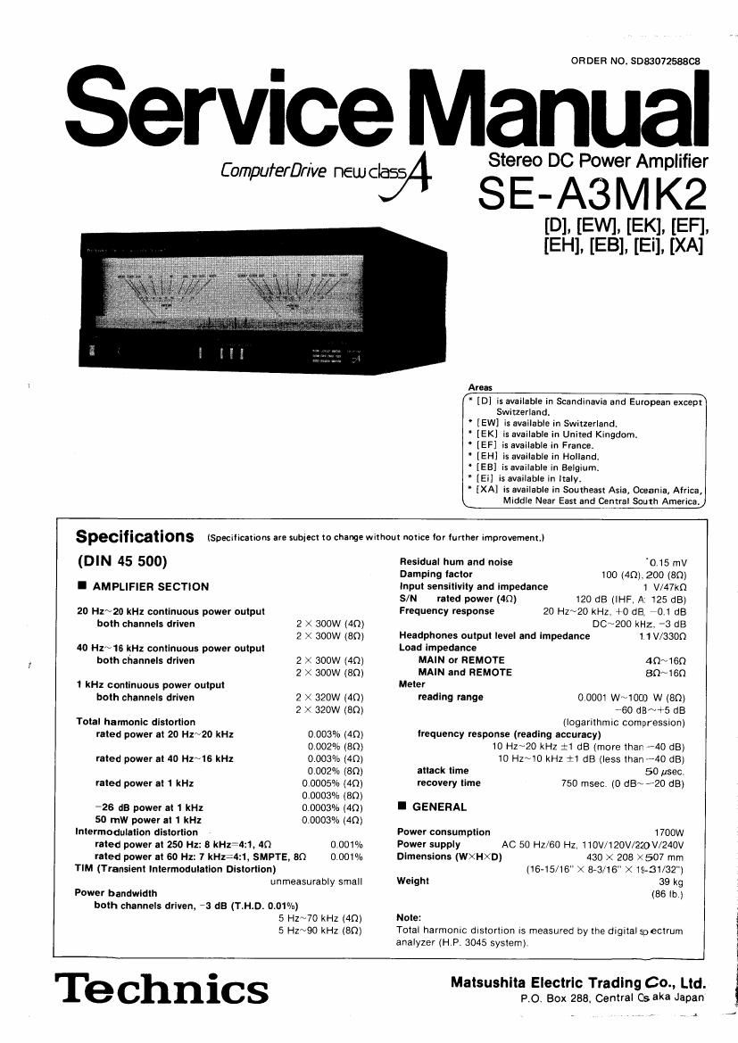
Technics SEA 3 Mk2 Service Manual

This is the 26 pages manual for Technics SEA 3 Mk2 Service Manual.
Read or download the pdf for free. If you want to contribute, please mail your pdfs to info@audioservicemanuals.com.

Page: 1 / 26
left right
Technics SEA 3 Mk2 Service Manual

Extracted text from Technics SEA 3 Mk2 Service Manual (Ocr-read)


Page 1

OR DER N0. SD83072588C8

Seryimcmeyanual

Stereo DC Power Amplifier

SE-A3M K2

[D]. [EWL [EK]. [EF].
[EH], [EB], [El]. [XA]

Areas

[D] is available in Scandinavia and European excep?
Switzerland.

[EW] is available in Switzerland.

[EK] is available in United Kingdom.

" [EF] is available in France.

" [EH] is available in Holland.

[EB] is available in Belgium.

* [Ei] is available in ltaly.

" iXA] is available in Southeast Asia, Oceania, Africa,

Middle Near East and Central South America.

Specifications (Specifications are subject to change without notice for further improvement.)

(DIN 45 500)
I AMPLIFIER SECTION

20 Hz~20 kHz continuous power output

both channels driven 2 X 300W (40)
2 X 300W (80)
40 Hz~16 kHz continuous power output
both channels drlven 2 X 300W (4m
2 x 300w (an)

1 kHz continuous power output
both channels driven 2 X 320W (40)
2 >< 320w (80)
Total harmonic distortion
rated power at 20 Hz~20 kHz 0 003% (40)
0.002% (80)
0.003% (40)
0.002% (8Q)
0.0005% (40)
0.000304, (80)
0.0003% (40)
0,0003% (40)

rated power at 40 Hz~16 kHz
rated power at 1 kHz

-26 its power at 1 kHz
50 mw power at 1 kHz
lntermodulation distortion
rated power at 250 Hz: 8 kHz=4:1, 40 0.001%
rated power at 60 Hz: 7 kHz:4:1, SMPTE, 80 0.001%
TIM (Transient lntermodulation Distortion)
unmeasurably small
Power bandwidth
both channels driven, *3 dB (T.H.D. 0.01%)
5 Hz~70 kHz (40)
5 HZNQO kHz (89)

Residual hum and noise '0.15 mV
Damping lactor 100 (4(1). 200 (an)
input sensitivity and impedance 1 V/47kl'1

Frequency response

Headphones output level and Impedance 1 1 V/SSOQ
Load Impedance
MAIN or REMOTE 40~160
MAIN and REMOTE BOA/160

Meter

I GENERAL
Power consumption 1700W
Power supply

Dimensions (WXHXD)

Weight 39 kg

120 dB (IHF, A: 125 dB)
20 Hz~20 kHz, +0 dB, *0] dB
DC~200 kHz. *3 dB

rated power (40)

0,0001 W~1000 W (80)

60 dB~+5 dB

(logarithmic compression)
frequency response (reading accuracy)

10 Hz~20 kHz :1 dB (more than (40 dB)

10 Hz~10 kHz {:1 dB (less than #40 (:18)

attack time 50 usec.

recovery time 750 msec. (0 dB~ '20 dB)

reading range

AC 50 Hz/60 Hz. llOV/120V/220V/240V
430 X 208 X507 mm
(16-15/16 >< 8-3/16" X )9-31/32")

(56 lb)

Note:
Total harmonic distortion is measured by the digltal spectrum
analyzer (HP. 3045 system).

Technics

Matsushita Electric Trading 60., Ltd.
PO. Box 288, Central Osaka Japan

Page 2

I CONTENTS

Page
SAFETY PRECAUTION ....................... CIRCUIT BOARDS AND
BEFORE REPAIR AND ADJUSTMENT WIRING CONNECTION DIAGRAM ................ 18
LOCATION OF CONTROLS .................... PRINTED CIRCUIT BOARDS ................... 21
DISASSEMBLV INSTRUCTIONS .................. 3 REPLACEMENT PARTS LIST
CHECK POINTS FOR REPAIR ................... 7 (Cabinet and chassis parts) ...................... 27
LOCATION OF P.C.B ......................... 9 EXPLODED VIEWS ..........
MEASUREMENTS AND ADJUSTMENTS ............. 10 SCHEMATIC DIAGRAM ....................... 31
OPERATION OF ICO CONTROLLER ............... 13 REPLACEMENT PARTS LIST (Electric parts) .......... 38
BLOCK DIAGRAM .......................... 15 RESISTORS AND CAPACITORS .................. 39

I SAFETY PRECAUTION

. Before servicing, unplug the power cord to prevent an electric shock.

, When replacing parts, use only manufacturer's recommended components for safety.

Check the condition of the power cord. Replace if wear or damage is evident.

After servicing, be sure to restore the lead dress, insulation barriers, insulation papers, shields, etc.

Before returning the serviced equipment to the customer, be sure to make the following insulation resistance test to
prevent the customer from being exposed to a shock hazard.

.UPQN

I INSULATION RESISTANCE TEST

1. Unplug the power cord and short the two prongs of the plug with a jumper wire.

2. Turn on the power switch.

3. Measure the resistance value with Ohmmeter between the iumpered AC plug and each exposed metal cabinet part, such as
screwheads antenna, control shafts, handle brackets, etc. Equipment with antenna terminals should read between 3M9
and 5.2Mfl to all exposed parts. (Fig. A) Equipment without antenna terminals should read approximately infinity to
all exposed parts. (Fig. B)

Note: Some exposed parts may be isolated from the chassis by design. These will read infinity.

Antenna
terminal \

Exposed Exposed 9
metal metal
part part
Ohmmeter Ohmmeter
(Figs A) (Fig. 3)

Resistance = 3MQ-52 M9 Resistance = Approx 00

4. If the measurement is outside the specified limits, there is a possibility of a shock hazard. The equipment should be
repaired and rechecked before it is returned to the customer.

I BEFORE REPAIR AND ADJUSTMENT

1. Turn off the power supply and shortcircuit of power supply capacitors (Cl ~C4, 105V,22000pF) at resistance (about
1009, 10W) in order to discharge the charged voltage. Do not short between C1 ~ C4 by screwdriver. it may damage
the componet.

2. Before turning on the power supply after completion of repair, slowly apply the primary voltage by using a power supply
voltage controller to make sure that the consumed current is free of abnormality. The consumed current a1
50Hz/60Hz in no signal mode is shown below with respect to supply voltage 110V/120V/220V/240V.

Power supply voltage AC 110V AC 120V AC 220V AC 240V
50Hz 0.6A ~ 1.8A 0.5A ~ 1.7A 0.3A ~ 0.9A O.3A~ 0.9A
Consumed current
60Hz 0.5A ~ 1.7A 0.4A ~ 1.6A 0.2A ~ 0.8A 0.2A"~ 0.8A