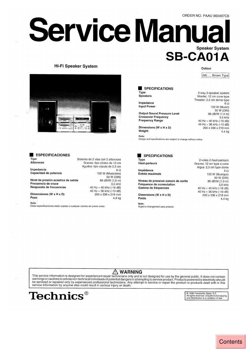
Technics SBCA 01 A Service Manual

This is the 4 pages manual for Technics SBCA 01 A Service Manual.
Read or download the pdf for free. If you want to contribute, please mail your pdfs to info@audioservicemanuals.com.

Page: 1 / 4
left right
Technics SBCA 01 A Service Manual

Extracted text from Technics SBCA 01 A Service Manual (Ocr-read)


Page 1

Hi-Fi Speaker System

I ESPECIFICACIONES

Tipo Sistema de 2 vias con 2 altavoces

Altavoces Graves: tipc cenico de 12 cm
Agudos: tipo cupula de 2,5 cm

impedancia 6 fl

Capacidad de potencia 100 W (Musicales)

50 W (DIN)
Nivei de presién acustica de salida 86 dE/W (1,0 m)
Frecuencia de cruce 3,5 kHz

Respuesta de lrecuencias 40 Hz = 40 kHz (-16 dB)
45 HZ = 36 kHz (-10 dB)
200 X 335 X 219 mm

4,4 kg

Dimensiones (W x H x D)
Peso

Nola:
Estas especiflcaciones estan suieias a cualquier camblo 5m previo aviso.

ORDER NO. PAAU 96049706

Service Manual

Speaker System

SB-CA01 A

I SPECIFICATIONS
Type
Speakers

Impedance
Input Power

Output Sound Pressure Level
Crossover Frequency
Frequency Range

Dimensions (W x H x D)
Weight

Note:

Colour

2-way 2-speaker system
Woofer: 12 cm cone type
Tweeter 2.5 cm dome type
5 I)

100 W (Music)

50 W (DIN)

86 (SM (1.0 m)

3.5 kHz

40 HZ = 40 kHZ (-16 dB)
45 Hz = 36 kHz (-10 dB)
200 X 336 x 219 mm

4.4 kg

Design and specificaiions are subject to Change wilhoui notice.

I SPECIFICATIONS

Type
Ha ut-parleurs

Impedance
Entrée maximale

Niveau de pression sonore de sortie
Fréquence de oonmutation
Gamma de fréquences

Dimensions (W x H x D)
Poids

Note:
Sujecl a changsmem sens preavis

2-voies 2-haui-parleurs
Graves; 12 cm type a cone
Aigus: 2,5 cm type dome
6 $2

100 W (Musique)

50 W (DlN)

86 dB/W (1.0 m)

3,5 kHz

40 Hz = 40 kHz (-16 clB)
45 Hz z 36 kHz (-10 dB)
200 X 335 X 219 mm

4.4 kg

service information by anyone else could result in serious injury or death.

A WARNING

This service information is designed ior experienced repair technicians only and is not designed for use by the general public, It does not contain
warnings or cautions to advise non technical individuals ofpotential dangers in attempting toservice product. Products powered by electricity should
be serviced or repaired only by experienced professional technicians. Any attempt to sen/ice or repair the product or products dealt with in this

Technics®

© 1996 Panasonic Spain SA.
Allrighisreserved Unauthorizedcopying
and distribution is a violation of law.

Contents

Page 2

SB-CAO1A

I DISASSEMBLY INSTRUCTIONS

Ref. No. 1 Removal of the Speaker Net Ref, No. 3 Removal of the Speaker Woofer

Procededure 1 Procededure 1 a 3

0 Remove the
4 screws.

' Remove the Speaker Net in lhe direction of arrow.

Ref No. 2 Removal of the Speaker Tweeter

Procededure 1 a 2

- Remove the Ornament
Woofer in the direction
ol lront part.

- Remove Ihe
4 screws.


S_ep 3

0 Remove the Speaker
Woofer in the direction
- Remove the Speaker of from part.
Tweeter in the direction ,
01 front pan, "

° Remove the 2
Speaker terminals.

~ Remove the 2
Speaker terminals.


Yellow

a 9

Screw Q 42 x 25 mm Screw 9 4.2 x 25 mm

,2-