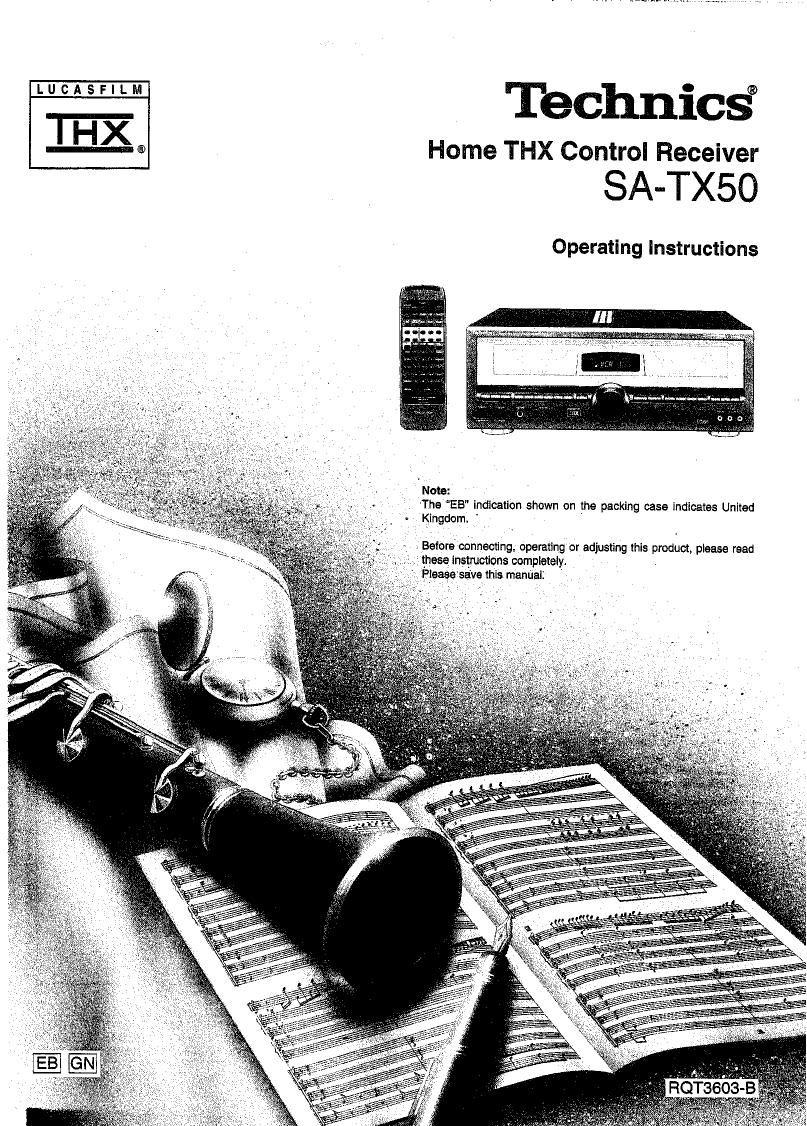
Technics SATX 50 Service Manual

This is the 36 pages manual for Technics SATX 50 Service Manual.
Read or download the pdf for free. If you want to contribute, please mail your pdfs to info@audioservicemanuals.com.

Page: 1 / 36
left right
Technics SATX 50 Service Manual

Extracted text from Technics SATX 50 Service Manual (Ocr-read)


Page 1

LUCASFILM

IHX

Technics®
® Home THX Control Receiver

SA-TXSO

Operating Instructions

Note:

'The "EB" indication shown on the packing case Indicates United
- Kingdom.

Before connecting. operating or adjusting this product. please read
these instructions completely.
Pleage saive thls mannalz

Page 2

Dear Customer

Thank you for purchasing this Technics product.
For optimum performance and safety, please read
these instructions carefully.

(For United Kingdom)

(EB" area code model only)
For your safety, please read the following text carefully.

This appliance is supplied with a moulded three pin mains plug
for your safety and convenience.

A 5-ampere fuse is fitted in this plug,

Should the fuse need to be replaced please ensure that the
replacement fuse has a rating of 5-ampere and that it is approved
by ASTA or BSI to BS1362.

Check for the ASTA mark ® or the BSI mark @ on the body of
the fuse.

lithe plug contains a removable fuse cover you must ensure that
it is refitted when the fuse is replaced.

If you lose the fuse cover the plug must not be used until a
replacement cover is obtained.

A replacement fuse cover can be purchased from your
local dealer.

CAUTIONI

IF THE FITTED MOULDED PLUG IS UNSUITABLE FOR
THE SOCKET OUTLET IN YOUR HOME THEN THE FUSE
SHOULD BE REMOVED AND THE PLUG CUT OFF AND
DISPOSED OF SAFELY.

THERE IS A DANGER OF SEVERE ELECTRICAL SHOCK
IF THE CUT OFF PLUG IS INSERTED INTO ANY 13-
AMPERE SOCKET.

If a new plug Is to be fitted please observe the wiring code as
shown below.
If in any doubt please consult a qualified electrician,

IMPORTANT

The wires In thls mains lead are coloured in accordance with the
following code:

Blue: Neutral. Brown: Live.

As these colours may not correspond with the coloured markings
identifying the terminals in your plug, proceed as follows:

The wire which is coloured Blue must be connected to the termi-
nal which is marked with the letter N or coloured Black or Blue.
The wire which is coloured Brown must be connected to the ter-
minal which is marked with the letter L or coloured Brown or Red.

Caution for AC mains lead

WARNING: Do NOT CONNECT EITHER WIRE TO THE
EARTH TERMINAL WHICH IS MARKED WITH THE LE'I'I'ER E,
BY THE EARTH SYMBOL 4- OR COLOURED GREEN OR
GREEN/YELLOW.

THIS PLUG IS NOT WATERPROOF-KEEP DRY.

Before use
Remove the connector cover.

How to replace the fuse

The location of the fuse differ according to the type of AC mains
plug (figures A and B). Confirm the AC malns plug fitted and fol-
low the instructions below. Illustrations may differ from actual AC
mains plug.

1. Open the fuse cover with a screwdriver.

Flgure A.

2. Replace the fuse and close or attach the fuse cover.

Figure A.

Fuse

%(5 ampere)

Fuse

(For Australia and NZ.)

THIS TUNER/RECEIVER IS CAPABLE OF RECEIVING THE NEW AM STEREO BROADCASTS FROM THE AM BAND RADIO STATIONS.
HOWEVER LIKE MANY TUNERS AND RECEIVERS CURRENTLY AVAILABLE ON THE MARKET IT WILL REPRODUCE THIS AM STEREO
SIGNAL ONLY IN AM MONO, WHICH, IN EFFECT, IS OF NO LESSER QUALITY THAN YOUR EXISTING AM MONO TUNER/RECEIVER,

m?

Page 7

Connecting video equipment

Stereo connection cable H (L) White

(not included) (R) Fled

Video connection cable m
(not included)

VCFi (not included)


VCR (not included) (playback only)

El 1:: Ci :1
o ani:|=' o all:i'=
'T-l ° OonO)---r| °QCZOOou0
AUDIO AUDIO VIDEO VIDEO VIDEO
OUT IN OUT IN OUT
{5 {g This unit
/ \
0 7g 5
5° in "'3
MO Wig:

O 0
VD mam
my: '"o @
|__.|
MonitorTV '"'
(not included) 9 %

Screen for

projector
(not included)

video projector
Video (not included)

Approx 6 mm\
Appliance inlet

Even when the connector is per-
fectly inserted. the from pan of
the connector jut out as shown
in the drawing.

However there is no problem

AC power supply usingihe unit.

cord (Included)

Connect this cord
after all other
cables and cords
are connected.

Household
I I u I - - --
t 6 AC outlet

_@ Household
AC outlet

(United Kingdom only)
BE SURE TO READ THE CAUTION FOR
THE AC POWER SUPPLY CORD 0N PAGE
2 BEFORE CONNECTION.

Page 20

-mlvmmn=_

MUTING

on»...

9%
L4

-_E!EJ/
@U 3 00

\-_-

-v

Um @© «7

K-l

Headphones l___r
(not included) BASS THEELE

Plug type: 0 O

6.3 mm phone plug

stereo type

1b adjust the tone quality

BASS
/0\
PM Turn THEBLE to adlust this high fre-

quency sound of the front left and
right speakers.

Turn BASS to adjust the low fre-
quency sound of the front Iett and
right speakers.

The above controls do not work In the DOLBY PRO LOGIC (THX
CINEMA, SURROUND, 3 STEREO) mode and the MONO mode.

Tb mute the sound level

MWNG Press MUTING.

l i

The message 'MUTlNG ON NOW" runs tepeatedly from right to left
across the display as long as the muting function is on.

Press once again to return to the previous volume level.

When the receiver is turned off. the muting operation will be auto-
matically cancelled.

To listen through headphones

Use VOLUME to reduce the volume level, and con-
nect the headphones.

If sound from speakers is not wanted, press SPEAKERS (A) and/or
(B) to turn off the speaker select indicators.

If you turn OFF both sets of speakers (A and B). you get normal
stereo playback trom the headphones with all playback modes.
Avoid listening for prolonged periods of time to prevent hearing
damage.

If sound output stops during use

It you make a mistake in operation or it sound output stops due to
some operation which was performed, the HELP function displays
characters which can be useful for indicating the method by which
this condition can be remedied.

ll "ERROR" or scrolling characters (for instance, "MUTlNG ON
NOW') appear on the display during operation. carry out the follow-
ing operation.

3a: Press HELP. (Touch only.)
ESE The method tor remedying this condition will be
displayed.

For your reference:

If the above button is pressed for a longer period until FlESET
appears on the display, the operation settings for the unit will be iniv
tialized to the settings made at the time of shipment.

However, any broadcasting stations which have been preset into
memory will not be erased at this time.