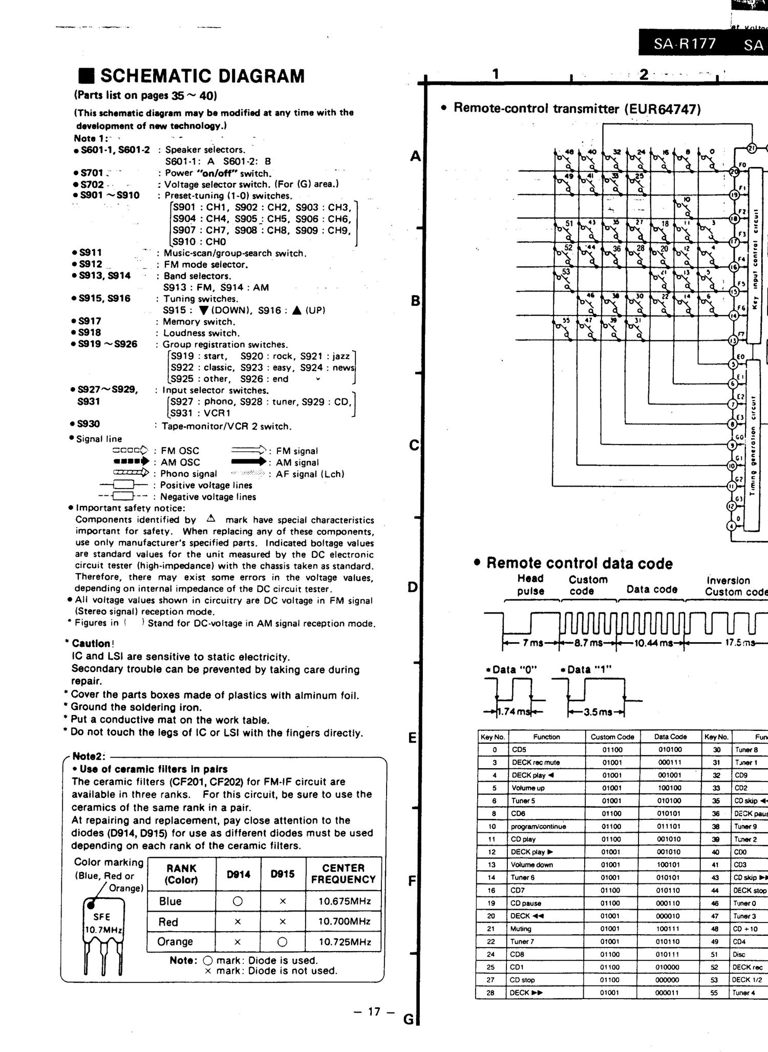
Technics SAR 177 Schematics

This is the 9 pages manual for Technics SAR 177 Schematics.
Read or download the pdf for free. If you want to contribute, please mail your pdfs to info@audioservicemanuals.com.

Page: 1 / 9
left right
Technics SAR 177 Schematics

Extracted text from Technics SAR 177 Schematics (Ocr-read)


Page 1

I SCH EMATIC DIAGRAM

(Parts list on pages 35 ~ 40)

(This schematic diagram may be modified at any time with the

development of new technologyJ

Noteiz" 1 '* ' .

08601-1, 8601-2 : Speaker selectors. "
5601-1: A 3601-2: 8

08701;" " ': Power "on/off" switch.

08702 - '_ ,. : Voltage selector switch. (For (G) area.)

08901 ~8910 : Preset-tuning (i-Ol switches. » » ,

' . 8901 :CHi, 8902 : CH2, $903 : CH3,
8904 :CH4, $905_: CH5. $906 : CH6,
$907 : CH7, $908 :CH8. $909 : CH9.
8910.: CHO

08911 -. ' : Musicscan/group-search switch.

08912 " : FM mode selector.

08913, $914 : Band selectors.

- $913 : FM, 8914 : AM

0 8915, 8916 : Tuning switches.

.1 8915: ViDOWNl, 8916: A (UP)

08917 : Memory switch.

08918 : Loudness switch.

0 8919 ~S926 : Group registration switches.

[8919 : start, 8920 : rock, 3921 :jazz]
8922 : classic, 8923 : easy, 5924 : news
8925 : other, 8926 : and v
08927~8929, : Input selector switches.
$931 [$927 : phone, 8928 : tuner, 8929 : C0,]
8931 :VCR1
° 5930 I Tape-monitor/VCFi 2 switch.

'Signal line
20000 : FM osc fl: FM signal
ll"? : AM OSC : AM signal
m : Phono signal "*"¢-'--*r-'-"-?=--'-FE*- : AF signal (Lchl
L; : Positive voltage lines
-- *- : Negative voltage lines
0 important safety notice:
Components identified by A mark have special characteristics
important for safety. When replacing any of these components,
use only manufacturers specified parts. Indicated boltage values
are standard values for the unit measured by the DC electronic
circuit tester (high-impedance) with the chassis taken as Standard.
Therefore, there may exist some errors in the voltage values,
depending on internal impedance of the DC circuit tester.
0 All voltage values shown in circuitry are DC voltage in PM signal
(Stereo signal) reception mode.
" Figures in i l Stand for DC-voltage in AM signal reception mode.

* Caution!
IC and LSi are sensitive to static electricity.
Secondary trouble can be prevented by taking care during
repair.
* Cover the parts boxes made of plastics with alminum foil.
" Ground the soldering iron.
" Put a conductive mat on the work table. .
" Do not touch the legs of IC or L8! with the fingers directly.

/ "0102: 1
0 Use 01 ceramic filters in pairs

The ceramic filters (CF201, CF202) for FM-lF circuit are
available in three ranks. For this circuit, be sure to use the
ceramics of the same rank in a pair.

At repairing and replacement, pay close attention to the
diodes (D914, 0915) for use as different diodes must be used
depending on each rank of the ceramic lilters.

Color marking j
RANK CENTER
(Blue, Red or (Com 99 5 FREQUENCY

1 T A *'

Blue 0 x 10.675MHz
sre * 4 E

Red x x 10.700111 Hz

10.7MHz - r l
Orange I x O 10.725MH2

ll

Note: 0 mark: Diode is used.
x mark: Diode is not used.

-17_

SA-Ri77

1 _ . . ,2. .. .y


I w r

1» Remote-control transmitter (EUIR64747)

Key input control cucmi

T imrng generation circuit

0 Remote control data code

HOBd Custom inversion
pulse code Data 0009 Custom code
I-! W
71113 8.7 ms 10.44 ma 17.5 013-
:Data "0" coats ."1"

.74 m 3.5 ms
Key No. Function Custom Code Data Code Key No.1 Fun
0 cos 01100 010100 30 Tuner8
3 1 DECK rec mute 01001 000111 31 Door 1
4 IOECK play 4 1 01001 001001 32 009 fi
5 .1 Volume up J 01001 100100 33 T002 #
6 _ Tuner 5 W 01301 i 010100 35 Cl) skip 4:
a . cos . 01100 1 010101 1 as » DECK 0mg
10 .1 program/continue J. 01100 4 011101 38 Tuner9 fl
11 CD play 01100 001010 I 39 Tuner 2
12 * DECK play > 01001 001010 40 000 C
13 *Volumedown . 01001 100101 J 41 1003 4
14 fi-Tunors T 01001 010101 ' 43 00 skip n
16 007 01100 010110 44 DECK stop
19 CD pause I 01100 1r 000110 46 Tunero
20 DECK 4< 01001 000010 47 Tuner 3
21 Muting 01001 1 100111 4a 7.70 +10
22 h Tuner 7 01001 010110 1 49 004 :
24 cos 01100 010111 51 1 Disc
25 001 01100 010000 52 DECK rec
27 ' CD stop 01100 000000 53 DECK 1/2 4
20 DECK DD V 01001 000011 55 Tuner 4