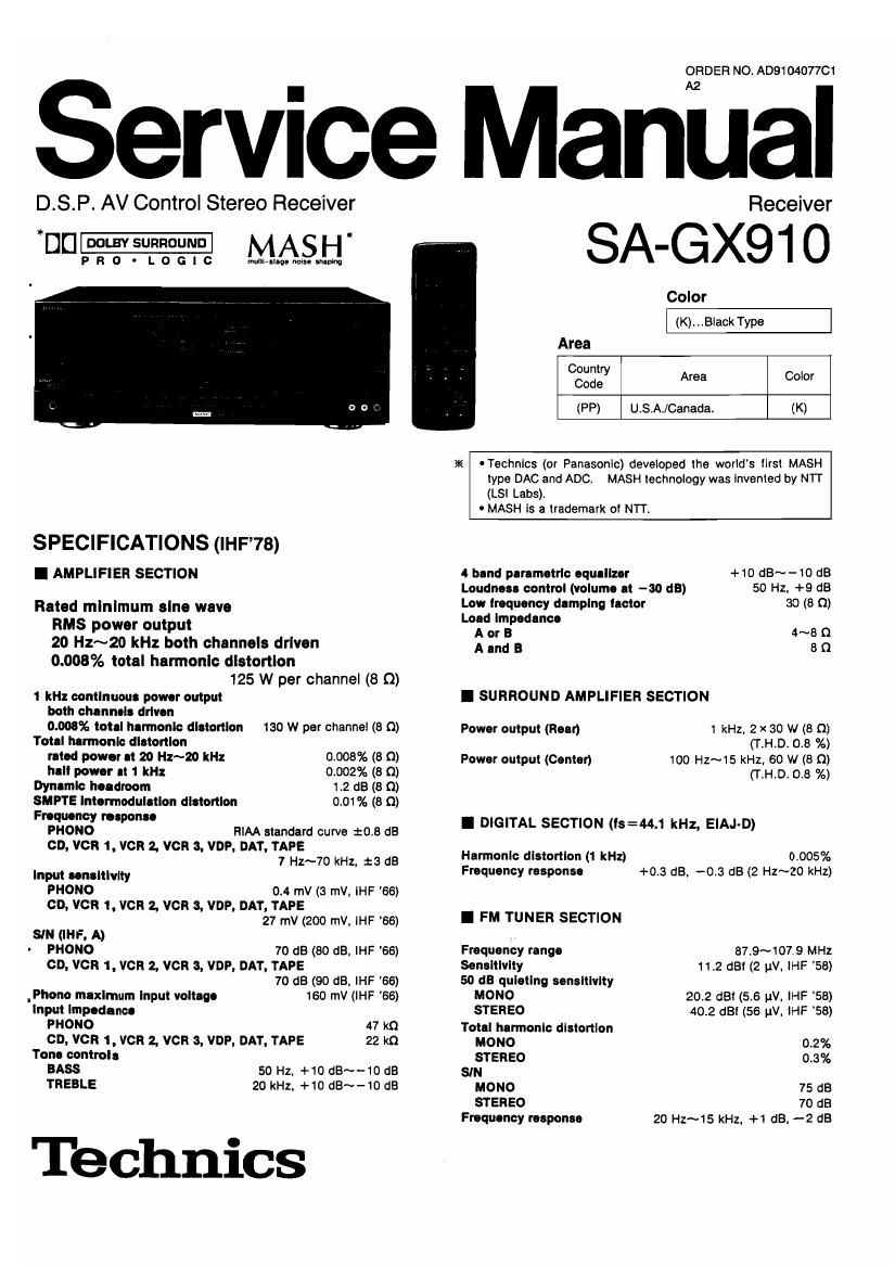
Technics SAGX 910 Service Manual

This is the 68 pages manual for Technics SAGX 910 Service Manual.
Read or download the pdf for free. If you want to contribute, please mail your pdfs to info@audioservicemanuals.com.

Page: 1 / 68
left right
Technics SAGX 910 Service Manual

Extracted text from Technics SAGX 910 Service Manual (Ocr-read)


Page 2

SA-GX91 0

Alternate channel selectivity 65 dB
Capture ratio 1.0 dB
Image rejection at 98 MHz 50 dB
IF mleetlon et 98 MHz 90 dB
Spurious response rejection at u MHz 80 dB
All suppression 50 dB
Stereo separation

1 kHz 40 dB

10 kHz 30 dB
Carrier leek

19 Ill-Ix -35 dB

30 kHz -50 dB

Antenna tennlnlll 75 Q (unbalanced)

I AM TUNER SECTION

Frequency range 530~1720 kHz
Sensitivity 20 11V. 330 pVIm
Selectivity 55 as
Image rejection It 1000 kHz 40 dB
IF relectlon It 1000 kHz 60 as

I VIDEO SECTION

Output voltage at 1 V Input (unbalanced) 1 x 0.1 Vpp
Maximum Input voltage 1.5 Vpp
Inputloutput Impedance 75 Q (unbalanced)
I CONTENTS

Page
SAFETY PRECAUTION ............................. 2. 3
ACCESSORIES ............... . .. 3
CONNECTIONS ................. .3~5
REAR PANEL TERMINALS AND FUNCTIONS .5~7

FRONT PANEL CONTROLS AND FUNCTIONS
DISASSEMBLY INSTRUCTIONS

DISASSEMBLY INSTRUCTIONS(REMOTE CONTROLLER) . . . . 22
TROUBLESHOOTING (REMOTE CONTROLLER) .............. 23
INITIALIZATION AFTER REPLACEMENT OF LCD.

CPU OR S-RAM (REMOTE CONTROLLER) .................. 23
PROTECTION CIRCUITRY ........... 24
BEFORE REPAIR AND ADJUSTMENT. 24

MEASUREMENTS AND ADJUSTMENT .
DESCRIPTION OF FL PANEL .............................. 25, 26

I S VIDEO SECTION
Rated Input, Rated output/Impedance
Y 1 Von. 1 Vp-p/75 Q
C 0.286 vrrp. 0.255 Vp-p/75 n
I GENERAL

500 W, 650 VA

AC 120V. 60Hz

430 x 158 x 429 mm
(16-15I16" x 6-7/32"x16-7l8")

Power consumption
Power supply
Dimensions (w x H x D)

Weight 15.2 kg (33.4 lb.)

Notes:

1. Total harmonic distortion is measured by the digital spectrum
analyzer.

2. Specifications are subject to change without notice. Weight
and dimensions are approximate.

Manufactured under license tram Dolby Laboratories
Licensing Corporation. Additionally licenced under one or
more of the following patents: U.S. numbers 3,632,886,
3,746,792 and 3,959,590; Canadian numbers 1,004,603 and
1,037,877.

Dolby" and the double-D symbol are trademarks of Dolby
Laboratories Licensing Corporation.


Page

BLOCK DIAGRAM ................. 27~30
SCHEMATIC DIAGRAM ........................ . . 31 ~50
SCHEMATIC DIAGRAM (REMOTE CONTROLLER) ........ 50~52
PRINTED CIRCUIT BOARDS AND WIRING CONNECTION

DIAGRAM (REMOTE CONTROLLER) ................... 53, 54
PRINTED CIRCUIT BOARDS ..........
WIRING CONNECTION DIAGRAM ......................
TERMINAL GUIDE OF ICS,

TRANSISTORS AND DIODES. .
FUNCTIONS OF IC TERMINALS
REPLACEMENT PARTS LIST. . . .
CABINET PARTS LOCATION .............................. 79, 80
CABINET PARTS LOCATION (REMOTE CONTROLLER). . . . . . 82
PACKING .................................................. 82

I SAFETY PRECAUTION (This safety precaution" is applied only in USA.)

1. Before servicing. unplug the power cord to prevent an electric shock.

2. When replacing parts, use only manufacturers recommended components for safety.

3. Check the condition of the power cord. Replace il wear or damage is evident.

4. After servicing, be sure to restore the lead dress. insulation berries, insulation papers. shields, etc.

5. Before returning the serviced equipment to the customer, be sure to make the following insulation resistance test to prevent the

customer from being exposed to a shock hazard.
OINSULATION RESISTANCE TEST

1. Unplug the power cord and short the two prongs oi the plug with aiumper wire.

2. Tum on the power swltch.

3. Measure the resistance value with ohmmeter between the jumpered AC plug and each exposed metal cabinet part. such as
screwheads antenna, control shalts, handle brackets, etc. Equipment with antenna terminals should read between 3 M0 and
5.2 M910 all exposed parts. (Fig. A) Equipment without antenna terminals should read approximately infinity to all exposed

parts. (Fig. 8)

Page 12

SA-GX910

Eli EB IE
0 SURROUND
i>oou3y
[>HALL SAMPLING
Dam, resousucv
i>staolum
73.33 a. 5;..2 W -
M
40 as iooisozsosoosao 1k 1.8k25k4k askioktzsk "z'
:CEARTZAM STEREO LT [\T/I 9,] [(-M q-_ csmnorrnonmtsnmrom-rssr
kH
33 gm /_//7 117 /_7 El 331m; Whigs; am Ax
EH El El

Fine mode Indicator (FINE)

This indicator illuminates when the fine mode select button is
selected in the parametric E0 mode.

Parametric E0 system center frequency
display
it displays the center frequency at the curves In the
parametric E0 rnode arranged by the user with the parametric
50 system or the curves pre-stored in this units memory.

Parametric E0 system operation select
Indicators (MAN UALIFIXED)
One of these indicators will Illuminate in accordance with the
fixed preset button or equalization preset buttons setting.

Manualltlxed preset indicators
(1 2 3 FLAT)
It displays the type oi curve selected with the equalization
preset buttons or tixed preset button in the parametric EQ
mode.

[8:] Parametric E0 system memory indicator (M)
This indicator illuminates when the parametric E0 system
memory button is pressed In the parametric EQ mode.

EI Parametric E0 system ott indicator (OFF)

This indicator illuminates when the parametric E0 system is
oit.

Tone mode Indicator (TONE MODE)

This indicator illuminates when the parametric EOltone mode
select button is set to the tone mode.

_12_

Parametric E0 mode indicator (P.E0 MODE)
This indicator Illuminates when the parametric EQ/tone mode
select button Is set to the parametric E0 mode.

Surround mode display (sunnouno)
This display shows the surround mode selected by the sur-
round mode select button.

Delay time display (DELAY TIME)
This display shows the length of the delay time selected for the
surround feature.

VDP Indicator (VDP)
This indicator illuminates when the input selector marked
VDF is pressed

Dolby 3 stereo indicator (DOLBY 3 STEREO)
This Indicator illuminates when the Dolby 3 stereo ON/OFF
button is switched 0N.

Dolby Pro-Logic Surround Indicator
(DU PRO-LOGIC)

This indicator illuminates when the Dolby Pro-Logic surround
mode Is selected.

Sampling trequency Indicators
(SAMPLING FREQUENCY)

The appropriate indicator wlii illuminate whenever a digital

signal with one of the sampling frequencies listed below is

detected at a "DIGITAL" terminal on the rear panel oi this

unit.

32 kHz: For digital signals with the sampling frequency of 32
kHz mode

44.1 kHz: CD and others

48 kHz: For digital signals with the sampling irequen cy oi 48
kHz mode

Note: Some digital components (compact disc player. etc.)

emit digital signals whenever their power switches are

on t

Page 19

SA-GX91 0

F Ref. No. Removal of the speaker impedance Ref. No. Removal of the AC IN/AC OUTLETS
20 switch P.C.B. 21 P.C.B.
Procedure Procedure
1-) 20 o 1-5109 21
.2 o Claws
)

Speaker Impedance
D swltch RC. 5.

1 . Remove the 2 screws (0, e).

2. Remove the speaker impedance switch P.C.B. in the direction of

Rear chassis
AC IN/AC

OUTLETS
P C. B.

0 Release the 6 claws.

arrow.
22m Removal of the fan motor
Procedure
1-»10->22 CW5
a an e
-. m a
00 000 o o D
Q 0 0 El
DOD 00000000000
0 oooooooooooo (Fig.2)
lit
Rear chassis Fan motor
(Fig. 1) °"

. Release the 3 claws. (See Fig. 1)
2. Insert a screwdriver at the root of the cooling fan.
Force it out of the motor shaft. (See Fig. 2)

. Remove the motor from the fan casing. (See Fig, 4)

who

with the hole of the fan motor. (See Fig. 5)

. Remove the motor cover by used @ screwdriver. (See Fig. 3)

. When mounting the motor tan, align the tan oasing's projection

Protect Ion

a. mm. (Fig- 4)
(Fig. 5)

Ref. No.

23 How to check the digital P.C.B.

Procedure
1-)10->23

1. Remove the shield cover in the direction at arrow.

Fig. 2 Fig.3

Dlllilal PC B.

2. When checking the soldered surface of the digital P.C.B.;nd
replacing the parts, do as shown in the figure above.

_19_