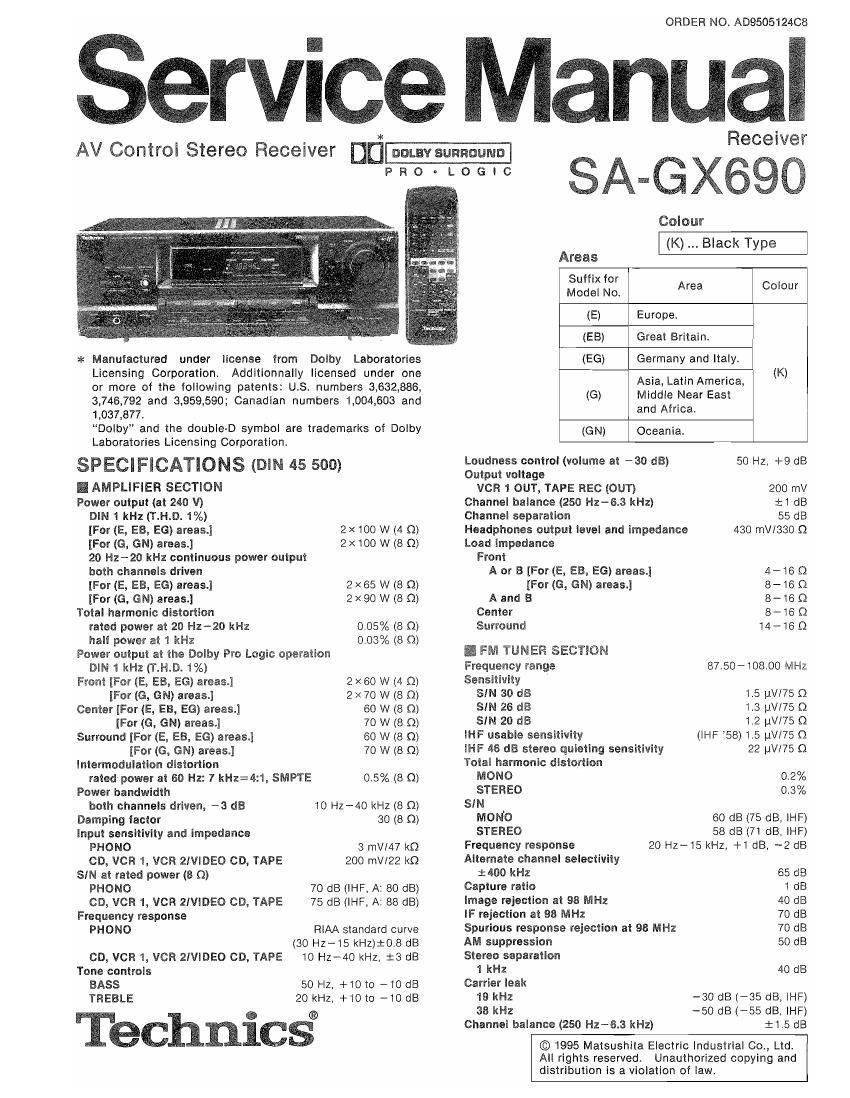
Technics SAGX 690 Service Manual

This is the 60 pages manual for Technics SAGX 690 Service Manual.
Read or download the pdf for free. If you want to contribute, please mail your pdfs to info@audioservicemanuals.com.

Page: 1 / 60
left right
Technics SAGX 690 Service Manual

Extracted text from Technics SAGX 690 Service Manual (Ocr-read)


Page 2

SA-GX690

A WARNING
This service information is designed for experienced repair technicians only and is not designed for use by the general public. It
does not contain warnings or cautions to advise non-technical individuals of potential dangers in attempting to service a product.
Products powered by electricity should be serviced or repaired only by experienced professional technicians.
or repair the product or products dealt with in this service information by anyone else could result in serious injury or death.

Any attempt to service

Limiting point 1.2 uV
Bandwidth
IF ampliiier 180 kHz
FM demodulator 1000 kHz

Antenna terminal(s) 75 Q (unbalanced)

I AM TUNER SECTION
0 For (E, EB) areas.
Frequency range

MW 522-1611 kHz (9 kHz steps)
530-1620 kHz (10 kHz steps)

LW 144 - 288 kHz
Sensitivity

MW 20 uv. 330 uVlm

LW 45 W
Selectivity

MW (at 999 kHz) 55 dB

LW (at 252 kHz) 55 dB
image rejection

MW (at 999 kHz) 40 dB

LW [at 252 kHz) 40 dB
IF rejection

MW (at 999 kHz) 55 dB

Lw (at 252 kHz) 55 dB

0 For (EG, G, GN) areas.
Frequency range 522-1611 kHz (9 kHz steps)
530-1520 kHz (10 kHz steps)

Selectivity (SIN 20 dB) 20 uV, 330 uV/m

I GENERAL
Power consumption (In standby condition: 3)

[For (E, EB, EG) areas.) 235 W
[For (G) area.) 240 W
[For (GN) area.) 225 W

Power supply

[For (E, EB, EG, GN) areas.) AC 50/60 HZ, 230-240 V

[For (G) area.) AC 50/60 Hz, 110- 127 V/220-240 V
Dimensions (W x H x D) 430 x 158 x 352 mm
Weight

[For (E, EB, EG, GN) areas.) 9.8 kg

[For (G) area.) 10.1 kg
I REMOTE CONTROL TRANSMITTER
Control keys

[For (E, EB, EG) areas.) 38 keys

[For (G, GN) areas.) 58 keys

Dimensions (WX H x D)
[For (E, E3, E6) areas.)
[For (G, GN) areas.)
Weight (including batteries)

52x24_5>< 176 mm
70X28x215 mm

[For (E, EB, EG) areas.) 104 9
[For (G, GN) areas.) 160 9
Power source Two UM-4/AAA

(Panasonic POIS/LROS or equivalent)

Notes:

1. Design and specifications are subject to change without notice.
Weight and dimensions are approximate.

2. Total harmonic distortions is measured by the digital spectrum
analyzer.

Selectivity at 999 kHz 55 dB
Image rejection at 999 kHz 40 dB
lF rejection at 999 kHz 55 dB
I VIDEO SECTION

Output voltage at 1 V input (unbalanced) 1 :0.1 Vp-p
Maximum input voltage 1.5 Vp-p

Inputloutput impedance

75 Q (unbalanced)

I CONTENTS

BEFORE REPAIR AND ADJUSTMENT.
CAUTIONS FOR AC MAINS LEAD.
PROTECTION CIRCUITRY.
FRONT PANEL CONTROL .
TO SET THE POWER VOLTAGE
ACCESSORIES ......................
EQUIPMENT CONNECTION
REMOTE CONTROL OPERATIO
OPERATION CHECK AND MAIN COMPONENT
REPLACEMENT PROCEDURE ..........

Page
19
20~24
25~39
40

OVERLOAD DETECTIONFUNCTION
BLOCK DIAGRAM .........
SCHEMATIC DIAGRAM
TERMINAL GUIDE OF ICS TRANSISTORS AND DIODES
TERMINAL GUIDE ................
WIRING CONNECTION DIAGRAM
PRINTED CIRCUIT BAORDS .....
REPLACEMENT PARTS LIST.
CABINET PARTS LOCATION .
RESISTORS AND CAPACITORS

43~49
. 50~53, so


FAN MOTOR TROUBLESHOOTING GUIDE PACKAGING ............................ .. 60
TROUBLESHOOTING .................................
I BEFORE REPAIR AND ADJUSTMENT
Disconnect AC power, Discharge both Power Supply Capacitors C703 and C704 (75V 7500uF), C705 and C706 (50V
3300uF) through a 100, SW resistor to ground.
DO NOT SHORT-CIRCUIT DIRECTLY (with a screwdriver blade, for instance), as this may distroy solid state devices.
After repairs are completed, restore power gradually using a variac, to avoid overcurrent.
Current consumption at 50Hz/60Hz in NO SIGNAL mode should be shown below with respect to supply voltage AC
230V/240V.
Power supply voltage AC 230V AC 240V AC 110- 127V AC 220-24OV
50 Hz 140~420mA 50 Hz 150~450mA 50 Hz 400~1000mA 50 HZ 150~450 mA
Consumed current 50/60 Hz
60H: 112~336mA 60 Hz 120~360mA 60 Hz 320~800mA 60Hz 120~360mA

HZW

Page 8

SAwGXSSO

[For (G, GN) areas] (RAK-SASOSMH)

To operate the receiver

Basic operations

To turn the power supply
ONIOFF

POWER Once the power has been set lo

To select an input
source

TUNER [:1 ON, it can be turned ON and OFF
[3 up simply by pressing POWER.

TAPE
TUNER CD VCR r vcn 2 MONlTOR VlDEO co
m

- PHONO can not be selected with thrs remote control.

0Selecting TAPE MONITOR turns ON the tape monitor
function. Pressing it again or another input select button
turns the function OFF

l

To turn on the Dolby Pro
Logic and select the
desired mode

Changes as follows each time the button is
pressed.
SURROUND vr 3 STEREO -r (OFF)

DUPRO LOGlC

(:1

we muse

V VCR
U [:1 Cl [:1

IDEDCD

lam)

To turn on the SFC
lunction and select the
desired mode

Changes as follows each time the button is

SFC pressed

C]

HALL!» LlVE THEATER
t-i SIMULATED a-l

o (i) duct r
<5 Cargo

3 cwozo cn/vop

To output a test signal

When the SURROUND or 3 STEREO mode rs ON

[:1

Press once more to stop the test srgnal

[iCJCJO

RELP 1 - CENYER s

-suarzou~o+

To adjust the output

When the SURROUND or 3 STEREO mode rs ON

receiver information and
procedures tor
remedying trouble

- CENTER 4»
EC) gag; level of the center [3 C) Output level cannot be changed when
(3 C] L: (3 speaker the surround mode IS ON and the center
13%;. .- 1-Day; DECKr/z models on PHANTOM.
m TC] [3 To adjust the output When the SURROUND or SFC mode rs ON
T « » « » " . level at the surround *SURROUNW'
C] l l C]
up? 1 speakers (:l (:J
l
C] [:LC] CI] 3 To turn the Dolby Pro OFF/ON
MUVlNG - VOLUME 4- _
[j [:] S LoglC/SFC OFF and ON C]
To dis la sim le
p y p HELP

(3

To adjust the delay time

When the SURROUND or SEC mode is ON
DEL/g
lM

To mute the sound level

The message MUTING ON NOW" runs
repeatedly from right to left across the display
as long as the muting function is on

Press once more to return to the original
volume.

MUTlNG

C]

To adjust the volume
level

- VOLUME +

Si:

Alter turnrng the power of the TV, VCR or laser disc player ON or OFF (see pages 5 -7) always
press TUNER belore pressing POWER when turning the power of the receiver ON and OFF,