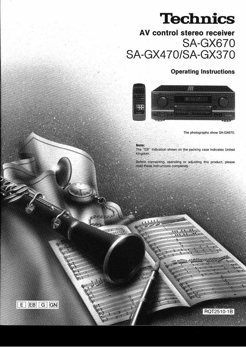
Technics SAGX 370 470 670 Owners Manual

This is the 28 pages manual for Technics SAGX 370 470 670 Owners Manual.
Read or download the pdf for free. If you want to contribute, please mail your pdfs to info@audioservicemanuals.com.

Page: 1 / 28
left right
Technics SAGX 370 470 670 Owners Manual

Extracted text from Technics SAGX 370 470 670 Owners Manual (Ocr-read)


Page 2

Dear Customer

Thank you for purchasing this Technics product.
For optimum performance and safety, please read
these instructions carefully.

These operating instructions are applicable to models
SA~GX870, SA-GX47CI and SAvGX370.

These operating instructions, however, are intended primarily
for model SAGX670.

(For areas except United Kingdom, Europe, Australia and
N.Z.)

CAUTION:

The AC voltage differs according to the area.
Be sure to set the proper voltage in your area
before use.

(For details, please refer to the page 8.)

(United Kingdom only)

(EB area code model only)

For your safety, please read the following text
carefully

This appliance is supplied with a moulded three pin
mains plug for your safety and convenience

A 5-ampere fuse is fitted in this plug.

Should the fuse need to be replaced please ensure
that the replacement fuse has a rating of 5-ampere
and that it is approved by ASTA or BSl to 881362
Check for the ASTA mark or the BSl mark @
on the body of the fuse.

if the plug contains a removable fuse cover you
must ensure that it is refitted when the fuse is replac-
ed.

if you lose the fuse cover the plug must not be used
until a replacement cover is obtained.

A replacement fuse cover can be purchased from
your local dealer.

CAUTION!

IF THE FITTED MOULDED PLUG IS UN-
SUITABLE FOR THE SOCKET OUTLET IN YOUR
HOME THEN THE FUSE SHOULD BE REMOVED
AND THE PLUG CUT OFF AND DISPOSED OF
SAFELY.

THERE IS A DANGER OF SEVERE ELECTRICAL
SHOCK IF THE CUT OFF PLUG IS INSERTED
INTO ANY 13-AMPERE SOCKET

li a new plug is to be fitted please observe the wiring
code as shown below.
If in any doubt please consult a qualified electrician

IMPORTANT
The wires in this mains lead are coloured in accor-
dance with the following code:

Blue: Neutral

Brown: Live
As the colours of the wires in the mains lead of this
appliance may not correspond with the coloured
markings identifying the terminals in your plug, pro-
ceed as follows:

Caution for AC mains lead

The wire which is coloured BLUE must be con-
nected to the terminal in the plug which is marked
with the letter N or coloured BLACK.

The wire which is coloured BROWN must be con.
nected to the terminal in the plug which is marked
with the letter L or coloured RED.

Under no circumstances should either of these
wires be connected to the earth terminal of the
three pin plug, marked with the letter E or the Earth
Symbol + .

Before use
Remove the connector cover as follows.

Connector
cover

How to replace the fuse
1. Remove the fuse cover with a screwdriver.

Fuse
(5 ampere)

(For Australia and N.Z.)

THIS TUNER/RECEIVER IS CAPABLE OF RECEIVING THE NEW AM STEREO BROADCASTS FROM THE AM BAND RADIO STATIONS.
HOWEVER LIKE MANY TUNERS AND RECEIVERS CURRENTLY AVAILABLE ON THE MARKET IT WILL REPRODUCE THIS AM STEREO
SIGNAL ONLY IN AM MONO. WHICH, IN EFFECT. IS OF NO LESSER QUALITY THAN YOUR EXISTING AM MONO TUNERIRECEIVER.

Page 22

Adjusting the output level of each speaker

In order to reproduce the feeling of movement of the sound and
clear orientation of sound, it is important to correctly adjust the
output levels of each speaker. Adjust to the correct levels while
listening to the test signalt

TEST

1 ""éAéé/lkéiag ' ' Has; 'A 1:} '3' it; (select the
0 speaker system to be used.

Illuminates


Press SURROUND o 3

STEREO to turn on the

desired mode.
For SURROUND mode


now:

nu . Ionic

0T

3 STEREO

Press TEST to output a test
signal.

mm on-

,mat:
in "'

Test signal sounds sequentially as
follows:

For SURROUND mode

Front speaker a Center speaker

(left)

1

Fiear speakers 4~-Front speaker
(left, right) (right)

For 3 STEREO mode
Front speaker
(left)

I-Front speaker (right) v-i

Center speaker

'4 """ v'éiu'n'né """ immature'ia'g'utiié
/ \ volume level normally used

tor enioying the source.

5 CENTER LEVEL Press CENTER LEVEL (-) or

-- (+) or REAR LEVEL (-) or
(+) to adjust the output level

balance.

SURROUND only

HEAR LEVEL Adjust the output levels of each
-- speaker at the listening position until
they are all identical.

{3 : Decrease the output level.
m EE] : Increase the output level.
art-.-

as

The output levels can be varied within
a range of 712 dB to +12 dB accor-
ding to the output levels from the front
speakers.

EST To stop the test signal
Press TEST,