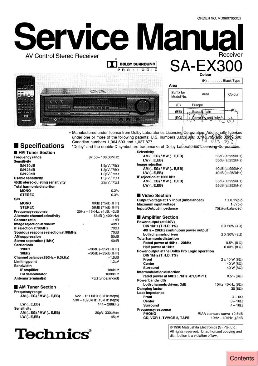
Technics SAEX 300 Service Manual

This is the 44 pages manual for Technics SAEX 300 Service Manual.
Read or download the pdf for free. If you want to contribute, please mail your pdfs to info@audioservicemanuals.com.

Page: 1 / 44
left right
Technics SAEX 300 Service Manual

Extracted text from Technics SAEX 300 Service Manual (Ocr-read)


Page 2

SA-EX300

information by anyone else could result in serious injury or death.

A WARNING
This service information is designed for experienced repair technicians only and is not designed for use by the general public. it does not contain
warnings orcautionsto advise norrtechnical individuals of potential dangers in attempting to service a product. Products powered by electricityshould
be serviced or repaired only by experienced professional technicians. Any attempt to sen/ice or repairthe product or products dealtwith in this service

Input sensitivity and impedance

PHONO SmV / 47kg

CD, VCR 1, TVIVCR 2, TAPE 200mV/22kfl
SIN at rated power (89)

PHONO 70dB (IHF, A: 80dB)

CD, VCR 1, TVIVCR 2, TAPE
Tone controls

75dB (IHF, A: 88dB)


BASS 50Hz, 11 WE

TREBLE 20kHz, 3:1 OdB
Outputvoltage

VCR 1, OUT, TAPE REC (OUT) 200mV
Channel balance (250Hz -6.3kHz) tidB
Channel separation 55dB
Headphones output level and Impedance 430mV l330§2
I Contents Page
CAUTION FOR AC MAINS LEAD .......... 2
BEFORE REPAIR ANDADJUSTMENT 3
PROTECTION CIRCUITRY ............... 3
TERMINAL GUIDE OF ICs TRANSISTORS AND DIODES 3

OPERATION CHECKS & MAIN COMPONENT REPLACEMENT 4 ~ 7
TROUBLESHOOTING ............
TERMINAL FUNCTION OF ICs

SCHEMATIC DIAGRAM ..........

I Caution for AC Mains Lead

I General
Power consu mptlon
Power supply

220W

For E, EB AC 50 Hz, 230- 240V

For EG AC 50 Hz, 230V
Dimensions (W x H x D) 430 X 136 X 358mm
Weight 8.7kg
Notes :

1. Specifications are subject to change without notice.
Weight and dimensions are approximate.
2. Total harmonic distortion is measured by the digital spectrum analyzer.

Page
BLOCK DIAGRAM ......................... . 26 ~ 29
WIRING CONNECTION DIAGRAM
PRINTED CIRCUIT BOARD
CABINET PARTS LOCATION
REPLACEMENT PARTS LIST
PACKAGING .......................
RESISTORS &CAPACITORS

[For [EB] area.]
For your safety, please read the following text carefully.

This appliance is supplied with a moulded three pin mains plug for
yoursafety and convenience. A 5-ampere fuse is fitted in this plug.
Should the fuse need to be replaced please ensure that the
replacement fuse has a rating of 5-ampere and that it is approved

by ASTA or BSI to BS1362. Check forthe ASTA mark orthe
as: mark @ on the body of the fuse.

CAUTION !

lF THE FITTED MOULDED PLUG IS UNSUITABLE FOR
THE SOCKET OUTLET IN YOUR HOME THEN THE
FUSE SHOULD BE REMOVED AND THE PLUG CUT
OFF AND DISPOSED OFF SAFELV.
THEREISADANGER OF SEVERE ELECTRICAL SHOCK
IF THE CUT OFF PLUG IS INSERTED INTO ANY 13-
AMPERE SOCKET.

If the plug contains a removable fuse cover you must ensure that
it is refitted when the fuse is replaced.

it you lose the fuse cover, the plug must not be used until a
replacement cover is obtained. A replacement fuse cover can be
purchased from your local dealer.

it a new plug is to be titted, please observe the wiring code as
shown below.
If in any doubt please consult a qualified electrician.

lM PORTANT
The wires in this lead are coloured in accordance with the following
code:
Blue: Neutral
Brown: Live
As the colours of the wires in the mains lead of this appliance may

not correspond with the coloured markings identifying theterminals
in your plug, proceed as follows:

Thewirewhich is coloured BLUE must be connectedtothe terminal
in the plug which is marked with the letter N or coloured BLACK.
The wire which is coloured BROWN must be connected to the
terminal inthe plug which is marked with the letter Lorcoloured RED.

Under no circumstances should either or these wires be connetced
to the earth terminal at the three pin plug, marked with the letter
E or the Earth symbol 4;.

Before use
Remove the connector cover as follows.

Connector
0 0 ve I

How to replace the fuse
1. Remove the fuse cover with a screwdriver.

Fuse cover

Fuse
(5 ampere)

Page 6

SA-EX300

I Main Component Replacement Procedures

1. Replacement of the Power IC and Regulator Transistor

Locate the nipper to the

thin portion or the joint. Nipper /

\

Cut the joint.

2. After cutting the ioints(6 ponions), bend the portions of the
bottom chassis assy in the direction of arrow with pliers.

1. Cut the ioints(6 portions) between bottom cover and CAUTION
bottom chassrs 3553' With me" a After replacing the power lc or regulatortrénsistor, apply
a sufficient quantity of compound grease (RFKXOOOZ)

between the heat sink and the power IC or regulator transistor.

Unsolderthe terminals 0' Power '0 0' (Radiation of power to & transistor)
regulator transistor

0 Tighten enough the screws after replacing the power IC or

re ulator transistor.
0t erwise, the heat radiation works little.

3. When replacing the power lC or regulator transistor,
unsolder the terminals of power IC or regulator transistor
on the soldered suitace.

Q 4 Then remove the screws fixed to the power IC or

transistor holder.
5. When installing or removing the power IC or transistor

holder. be sure to use an oflset screwdriver.


* Upset the bottom cover

6. After replacing the power [C or regulator transistor, upset
the bottom cover and align the ribs of the bottom cover to
the lugs on the bottom chassis assy.

7. After mounting the bottom cover on the bottom chassis
assy, fix it with a screw(XTBS+8J).