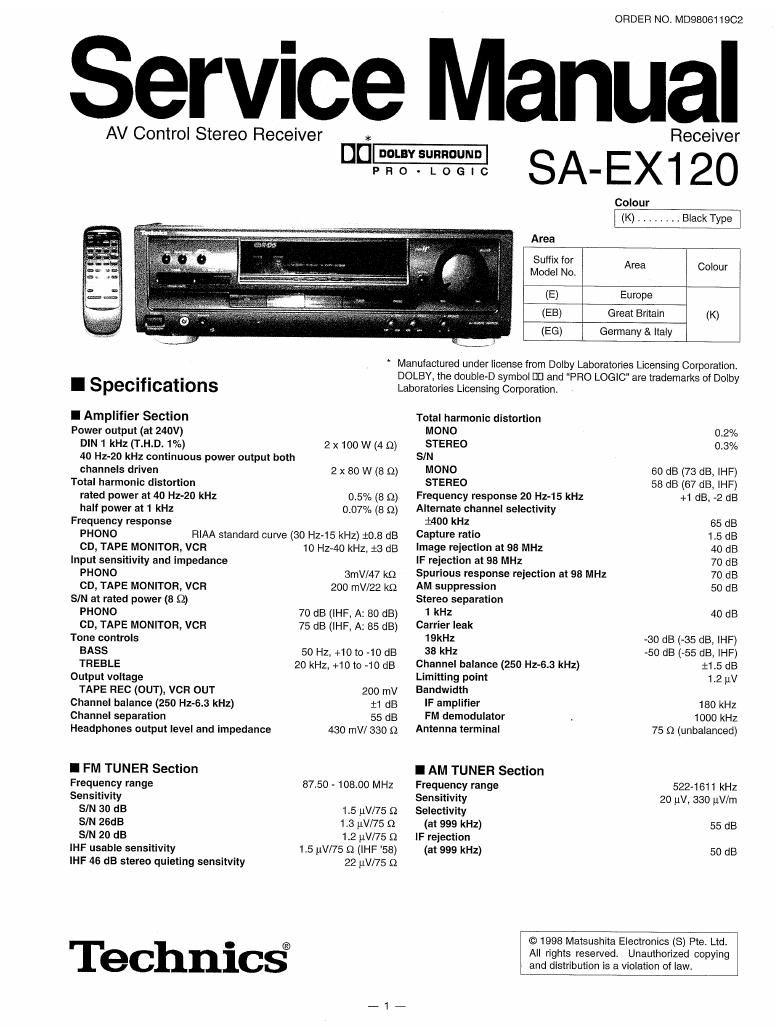
Technics SAEX 120 Service Manual

This is the 44 pages manual for Technics SAEX 120 Service Manual.
Read or download the pdf for free. If you want to contribute, please mail your pdfs to info@audioservicemanuals.com.

Page: 1 / 44
left right
Technics SAEX 120 Service Manual

Extracted text from Technics SAEX 120 Service Manual (Ocr-read)


Page 2

SA-EX1 20

A WARNING

This service information is designed for experienced repair technicians only and is not designed for use by the general public. It does
not contain warnings or cautions to advise non-technical individuals of potential dangers in attempting to service a product. Products
powered by electricity should be serviced or repaired only by experienced professional technicians. Any attempt to service or repair the
product or products dealt with in this service information by anyone else could result in serious injury or death.


I General
Power supply [E,EG] AC; 280, 50Hz

[EB] AC; 230~24o v, 5on
Power Consumption 190 W
Dimensions 430 (W) x 136 (H) x 309 (D) mm
Weight 7.0 kg
I Contents

PAGE

- BEFORE REPAIR AND ADJUSTMENT. 2
- PROTECTION CIRCUITRY ................. 2
- CAUTION FOR AC MAINS LEAD 3
0 ACCESSORIES 4
- FRONT PANEL CONTROLS. 4
- EQUIPMENT CONNECTIONS 5
0 SPEAKER CONNECTIONS 6
' BASIC OPERATIONS 7 ~ 8
- LISTENING TO RADIO BROADCASTS. 9 ~ 11
- MAKING A RECORDING 12
- SLEEP TIMER FUNCTION . 13
. OPERATION CHECKS 14 ~17

I Before Repair and Adjustment

Notes :

1. Specifications are subject to change without notice,
Weight and dimensions are approximate.

2. Total harmonic distortion ls measured by the digital spectrum
analyzerr

PAGE

0 BLOCK DIAGRAM.................. 18 ~ 20

- TERMINAL FUNCTION OF [05. 21
- TERMINAL GUIDE OF ICs,

TRANSISTORS & DIODES. 22

° SCHEMATIC DIAGRAM .. 23 ~ 30

- WIRING CONNECTION DIAGRAM .
- PRINTED CIRCUIT BOARD .........
- CABINET PARTS LOCATION
' REPLACEMENT PARTS LIST ..
- RESISTORS & CAPACITORS ............... 41 ~ 48
° PACKING MATERIALS & ACCESSORIES 44
' PACKAGING .............................................................. 44

Disconnect AC power, discharge four Power Supply Capacitors (0703 to C706) through a 109, SW resistor to ground. DO NOT
SHORT-CIRCUIT DIRECTLY (with a screwdriver blade, for instance). as this may destroy solid state devices. After repairs are
completed, restore power gradually using a variac, to avoid overcurrent.

Current consumption at 230V - 240V, 50Hz in NO SIGNAL mode should be between 130mA to 190mA.

I Protection Circuitry

The protection circuitry may have operated if either of the follow-
ing conditions are noticed :

0 No sound is heard when the power is turned on.
- Sound stops during a performance.

The function of this circuitry is to prevent circuitry damage if, for
example, the positive and negative speaker connection wires
are "shorted, orifspeakersystems with an impedance less than
the indicated rated impedance of the amplifier are used.

If this occurs, follow the procedure outlines below:

1. Turn off the power.
2. Determine the cause of the problem and correct it.
3. Turn on the power once again after one minute.

Note:

When the protection circuitry functions, the unit will not operate
unless the power is first turned off and then on again.

Page 5

SA-EX120

I Equipment connections

Make sure that the power supply for all components has been turned off before making any connections.

Refer to the operating instructions of the equipment to be connected.

Do not place books, etc, on the top of this unit or block the heat radiation vents in any way.

2 Stereo connection cable (not included) Video connection cable (not included) E
E White (L)
E Red (R) -r n m Math- E
CD changer (or CD player)
(not included) Tape deck (not included)

REC UN)
[:1 n
== PLAY -:= E
on u DEDDDO CED (OUT :44
OUTPUT A
Cooling fan
The cooling tan operates at high
{6 4 power output levels onlyt
Only for turntable

with ground terminal

(on it, our in
© to © co «n
O O O 0 an
AC mains lead (included)
f? Household
AC outlet
AUDIO AUDIO F
lN QUT
GND OUTPUT a VIDEO VIDEO
__ [fin E' .utju ODUT IN E
0
LE; :9 oomoouo: ;L I r,
Turntable (not included) VCFl (not included) TV (not included)
AC mains lead
BE SURE TO READ THE CAUTION FOR THE AC Connect this mains lead after all other cables and cords are con-
MAINS LEAD ON PAGE 3 BEFORE THE FOL- "eced-

LOWiNG CONNECTION.

Insertion of Connector

Even when the connector is per-
fectly inserted, depending on the
type oi inlet used, the front part of

the connector may jut out as shown Approx. 6 mm
In the drawlng. A _ Appliance inlet
However there is no problem using

the unit.