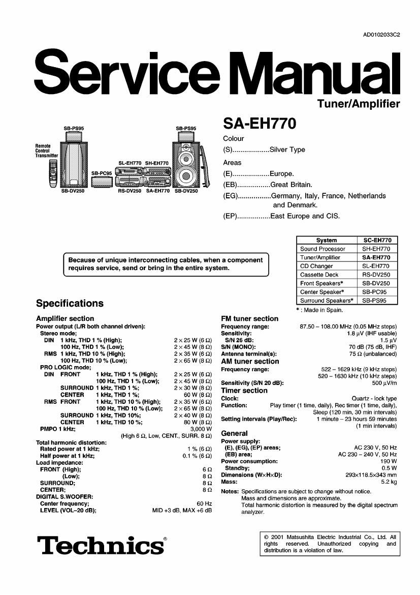
Technics SAEH 770 Service Manual

This is the 37 pages manual for Technics SAEH 770 Service Manual.
Read or download the pdf for free. If you want to contribute, please mail your pdfs to info@audioservicemanuals.com.

Page: 1 / 37
left right
Technics SAEH 770 Service Manual

Extracted text from Technics SAEH 770 Service Manual (Ocr-read)


Page 1

AD01 02033C2

Service Manual


Tu nerlAm pl ifier
SB-P395 senses SA' E H 770
xmxmx: mmi C 0' CU r
33% (S) ................... Silver Type
Transmitter
Areas
(E). .Europe.


.Great Britain.

FIS-DV250 SA-EH770 S

(EG)... .Germany, Italy, France, Netherlands
and Denmark.
(EP) ................. East Europe and CIS.
System Sc-EH770
Sound Processor SH-EH770
Because of unique interconnecting cables, when a component Tuner/Amp'ifie' SA'EH770
requires service, send or bring in the entire system. CD Changer SL'EH770
Cassette Deck RS-DV25O
Front Speakers" SBDV250
Center Speaker SB-PCQS
- - . 3*
Specifications Surround Speakers SB-PSQS
*2 Made in Spain.
Amplifier section FM tuner section
Power output (LIB both channel driven): Frequency range: 87.50- 108.00 MHz (0.05 MHz steps)
Stereo mode; Sensitivity: 1.8 (N (IHF usable)
DIN 1 kHz, THD 1 % (High); 2 x 25 w (6 n) SIN 26 115: 1.5 uv
100 Hz, THD1 °/. (Low); 2 X 45 w (3 o) SIN (MONO): 70 dB (75 dB, IHF)
RMS 1 kHz, THD 1D % (ngh); 2 x 35 W (6 Q) Antenna terminal(s): 75 Q (unbalanced)
100 Hz, THD 10 % (Low); 2 X 65 W (8 (2) AM tuner section
PR0 LOGIC mode; _ Frequency range: 522 - 1629 kHz (9 kHz steps)
DIN FRONT 1 kHz, THD 1 °/. (High); 2 x 25 w (6 n) 520 _ 1630 kHz (10 kHz steps)
00 ls THD 1 % (LOW); 2 X 45 W18 11> Sensitivity (SIN 20 are): soo uV/m
SURROUND 1 kHz, THD 1 31:; 2 X 30 W (8 Q) Timer section
CENTER 1 kHz, THD 1 %; 60 W (8 9) Cl k' Q n -l k t
RMS FRONT 1 kHz, THD 10 °/. (High); 2 x 35 w (6 9) F °° d , PI f 1 r d .1 R r 312 °°d We
100 Hz, THD 10 % (Low); 2 x 65 W (8 Q) unc on. ay imer( Ime, ai y), ec _Imer( _Ime, ally),
SURROUND 1 kHz, THD 10%; 2 X 40 w (8 9) . . 5'69? 20 mm 3° m'" 'me.a'5)
CENTER 1 kHz, THD 10 0/0; 80 W (B 9) Setting intervals (Play/Rec). 1 minute 7 23 ho1urs'50 rtnmuties
PMPO 1 kHz; 3.000 w ( min in erva 5)
(High 6 a, Low, CENT, SURR. s 9) General
Total harmonic distortion: P°We' SUPP'W
Rated power at 1 kHz; 1 % (6 g) (E). (EG), (EP) areins; AC 230 V, 50 Hz
Halt power at 1 kHz; 0.1 % (s 9) (EB) area: _ AC 230 - 240 v, 50 Hz
Load impedance: Power consumption: 190 W
FRONT (High); 6 o Standby; 0:5 W
(Low); 3 9 Dimensions (WXHXD): 293x118.5><343 mm
SURROUND; 8 (2 Mass: 5-2 k9
CENTER; 8 9 Notes: Specifications are subject to change without notice.
DIGITAL 5-WOOFER Mass and dimensions are approximate.
Center frequency; 60 H2 Total harmonic distortion is measured by the digital spectrum
LEVEL (VOL-20 dB); MID +3 dB, MAX +6 dB analyzer.

© 2001 Matsushita Electric Industrial Co., Ltd, All

0 ®
rights reserved. Unauthorized copying and
distribution is a violation of law.

Page 2

SA-EH770

A WARNING

This service information is designed for experienced repair technicians only and is not designed for use by the general public.

It does not contain warnings or cautions to advise non-technical individuals of potential dangers in attempting to service a product.
Products powered by electricity should be serviced or repaired only by experienced protessional technicians. Any attempt to service
or repair the product or products dealt with in this service information by anyone else could result in serious injury or death.

CONTENTS

Page
1 Before Repairs ------------------------------------------------------------------------ 2
2 Protection Circuitry --2

3 Accessories --

4 Caution for AC Mains Lea 4
5 Location of Controls --------------------------------------------------------------- 5
6 Operation Checks and Component Replacement Proceduress
6.1. Checking for the AC IN P.C.B. --------------------------------------- e
6.2. Checking for the operation P.C.B. ----------------------------------- e
6.3. Checking for the main P.C.B. ----------------------------------------- 7

6.4. Replacement for the regulator transistor- -- 8
6.5. Replacement for the power IC ------------ --8
7 To Supply Power Source -------------------------------------------------------- 9
8 Self-Diagnostic Function ------------------
8.1. To display the malfunction code --

1 Before Repairs

1.Turn off the power supply. Using a 10 Q. 10 W resistor,
connect both ends of power supply capacitors (C701, C703
and C702, C704) in order to discharge the voltage.

2. Before turning the power supply on. after completion of
repair, slowly apply the primary voltage by using a power
supply voltage controller to make sure that the consumed
current at 50 Hz in NO SIGNAL mode should be shown
below with respect to supply voltage 230/240 V.

AC 230 v | AC 240 v

100 ~ 350 mA

Power supply voltage
Consumed current 50 Hz

Page

8.2. To retum to the normal display ------------------------------------- 10

8.3. Display contents 1o

9 Schematic Diagram Notes 11
10 Schematic Diagram ------- 12
11 Printed Circuit Board Diagram ---------------------------------------------- 21
12 Type Illustration of le, Transistors and Diodes "-24
13 Wiring Connection Diagram ------------------------------- ...25
14 Block Diagram ---------------------------------------------------------------------- 26

15 Terminal Function of ICS ------------------------------------------------------ 31

15.1. IC901 (CZBBFDOOO297 System Control/FL Drive
16 Replacement Parts List --------------------------------------------
17 Cablnet Parts Location --------------------------------------------------------- 36
18 Packaging ----------------------------------------------------------------------------- 37

2 Protection Circuitry

The protection circuitry may have operated if either of the
following conditions is noticed:

. No sound is heard when the power is switched ON.

- Sound stops during a performance.
The functions 0t this circuitry is to prevent circuitry damage if.
for example, the positive and negative speaker connection
wires are shorted, or it speaker systems with an impedance
less than the indicated rated impedance of this unit are used.

If this occurs, follow the procedures outlined below.
1.Switch OFF the power.
2. Determine the cause of the problem and correct it.
3. Switch ON the power once again.

Note:

When the protection circuitry functions, the unit will not
operate unless the power is first switched OFF and then ON
again.