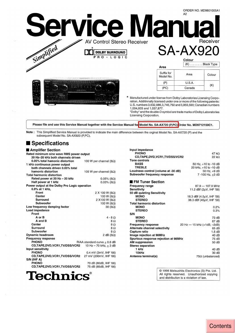
Technics SAAX 920 Service Manual

This is the 40 pages manual for Technics SAAX 920 Service Manual.
Read or download the pdf for free. If you want to contribute, please mail your pdfs to info@audioservicemanuals.com.

Page: 1 / 40
left right
Technics SAAX 920 Service Manual

Extracted text from Technics SAAX 920 Service Manual (Ocr-read)


Page 1

[iii

AV Control Stereo Receiver

ORDER NO. MD9801005A1

Receiver

SA-AX920

PRO-LOGIC

Colour
(K) .

Area
Suffix for
Model No. Area C°'°'

(P) U.S.A.

(K)
(PC) Canada

* Manufactured under license from Dolby Laboratories Licensing Corpo-
ration. Additinnally licensed underone or more ofthe following patents:
U.S. numbers 3,632,886,3,746,792 and 3,959,590; Canadian numbers
1,004,603 and 1,037,877.

IDolbyI and the double-D sym bol are trade marks of Dolby Laboratories
Licensing Corporation.

Please tile and use this Service Manual together with the Service Manual fo Model No. S )020 (P,Pc) D rder No. MD971215DC1.

Note : This Simplified Service Manual is provided to indicate the main difference between the orginal Model No. SA-AX720 (P) and the

subsequent Model No. SA-AX920 (RPC).

I Specifications

I Amplifier Section

Rated minimum sine wave RMS power output
20 Hz-20 kHz both channels driven
0.05% total hamonic distortion

1 kHz continuous power output
both channels driven 0.05% total
hamonic distortion

Total harmonic distortion

100 W per channel (89)

105 W per channel (89)

Rated power at 20 Hz - 20 kHz 0.05% (89)
Half power at 1 kHz 0.03% (89)
Power output at the Dolby Pro Logic operation
0.9% at 1 kHz,
Front 2 X 100 W (89)
Center 100 W (89)
Surround 2 X100 W (8(1)
Subwoofer 100 W (89)
Low frequency damping factor 30 (89)
Load impedance
Front
A or B 4 - B Q
A and B 8 (2
Center 8 Q
Surround B Q
Subwooler 8 {2
Dynamic headroom 2 dB (8(2)

Frequency response
PHONO FtlAA standard curve 1 0.8 dB
CD,TAPE,DVD,VCFt1,TVIDSSNCRZ 10 Hz - 70 kHz, 2 3 dB
Input sensitivity
PHONO 04 mV (3mV, lHF '66)
CD,TAPE,DVD,VCR1,TVIDSSNCRZ 27 mV (200mv, lHF '66)
SIN (lHF A)
PHONO 70 dB (80dB, lHF 86)
CD,TAPE,DVD,VCR1,TVIDSSNCRZ 75 dB (85dB, IHF '66)

Technics®

Input impedance

PHONO 47 k9

CD,TAPE,DVD,VCR1,TV/DSSNCR2 22 k9
Tone GOIHIOIS

BASS 50 HZ, +10 to -10 dB

TREBLE 20 kHz, +10 to -10 dB

Loudness control (volume at -30 dB)
Subwoofer frequency response

50 HZ, +9 dB
7 >100 Hz, :3 dB

I FM Tuner Section
Frequency range 87.9 - 107.9 MHz
Sensitivity 11.2 dBf (2w, lHF '58)
50 dB quieting Sensitivity

MONO 18.3 dBf (4t5uV, lHF 58)

STEREO 38.3 dBf (45uV, lHF '58)
Total harmonic distortion

MONO 0.2%

STEREO 0.3%
SIN

MONO 73 dB

STEREO 67 (:18
Frequency response 20 HZ- 15 kHz (+1dB. -2dB)
Alternate channel selectivity 65 dB
Capture ratio 1.5 dB
Image rejection at 98MHz 40 dB
Spurious response reiectlon at 98MHz 75 dB
AM suppression 50 dB
Stereo separation

1 kHz 40 dB

10kHz 30 dB

Antenna terminal(s) 759 (unbalanced)

© 1998 Matsushita Electronics (8) Pte. Ltd.
All rights reserved. Unauthorized copying
and distribution is a violation of law.

Contents

Page 2

SA-AX920
A: WARNING

This service information is designed tor experienced repair technicians only and is not designed (or use by the general public. It does
not contain warnings or cautions to advise nonvtechnical individuals at potential dangers in attempting to service a product. Products
powered by electricity shouid be serviced or repaired only by experienced professional technicians. Any attempt to service or repair
the product or products dealt with in this service information by anyone else could result in serious injury or death.

I AM Tuner Section
Frequency range 530 - 1710 kHz
Sensitivty ZOuV. SSOuV/m
Selectivity 55 dB
IF rejection at 1000kHz 50 dB
I Video Section
Output voltage at 1 V input (unbalanced) 120.1 Vp-p
Maximum input voltage 1.5 Vp-p
lnputJoutput impedance 75 Q
I General
Power consumption 350 W (In standby condition : 2W)
Power supply AC 120V. 60 Hz
Dimensions (W x H x D) 430 x 158 x 312 mm
(ISIS/u; x 67/3; x 129/32)
Weight 93 kg (21.3 lb.)
Notes :

1. Specifications are subject to change without notice
Weight and dimensions are approximate.
21 Total harmonic distortion is measured by the digital spectrum

analyzerl
I Contents

PAGE
- BLOCK DIAGRAM ............................. 3 _ 7
- SCHEMATIC DIAGRAM . , e - 23
- PRINTED CIRCUIT BOARD , , 24- so
-WIRING DIAGRAM .. 31
. CABINET PARTS LOCATION 32
' REPLACEMENT PARTS LIST . 33 ~ 35
- RESISTOHS & CAPACITORS . as - 4o
' PACKAGING 40