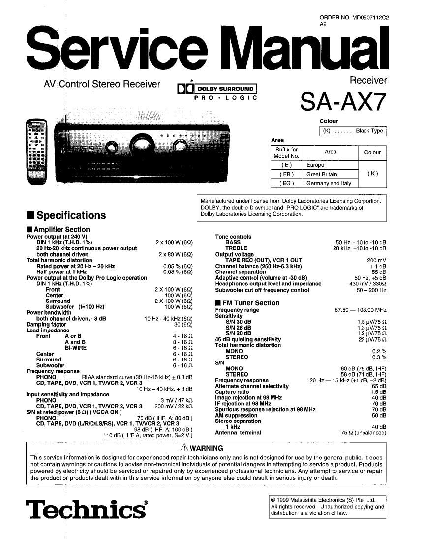
Technics SAAX 7 Service Manual

This is the 60 pages manual for Technics SAAX 7 Service Manual.
Read or download the pdf for free. If you want to contribute, please mail your pdfs to info@audioservicemanuals.com.

Page: 1 / 60
left right
Technics SAAX 7 Service Manual

Extracted text from Technics SAAX 7 Service Manual (Ocr-read)


Page 1

ORDER NO. MD990711202
A2

Service Manual

AV Cpntrol Stereo Receiver Dfi- Receiver

Pno-Loeic SA_AX7

Colour
(K) ........ Black Type
Area
( E ) Europe
( EB) Great Britain (K)
( EG ) Germany and Italy

Manufactured under license from Dolby Laboratories Licensing Corportion.
DOLBY, the doubleD symbol and "PRO LOGIC" are trademarks of

I Specifications Dolby Laboratories Licensing Corporation.
I Amplifier Section
Power output (at 240 V) Tone controls
DIN1 kHz(T.H.D.1°/o) 2 x 100 W (65)) BASS 50 H2. +10 to ~10 dB
20 Hz-20 kHz continuous power output TREBLE 20 kHz. +10 to -10 dB
both channel driven 2 x 80 W (69) Output voltage
Total harmonic distortion TAPE REC (OUT), VCR 1 OUT 200 mV
Rated power at 20 Hz - 20 kHz 005 % (60) Channel balance (250 Hz~6.3 kHz) 1 1 dB
Halt power at 1 kHz 0.03 % (69) Channel separation 55 dB
Power output at the Dolby Pro Logic operation Adaptive control (volume at -30 dB) 50 Hz, +5 dB
DIN 1 kHz (T.H.D. 1%) Headphones output level and Impedance 430 mV / 3309
Front 2 X 100 W (69) Subwooter cut oil lrequency control 50 - 200 Hz
Center . 100 w (on)
summid 2 X 100 W (69) I FM Tuner Section
Power Iii? {fir (E100 Hz) 100 W (69) Frequency range 87.50 - 108.00 MHz
both channel driven, -a dB 10 Hz - 40 kHz (so) Sang/233% as 1 5 W75 9
WWW 3" 3° (6") SIN 26 dB 1.3 fivns n
Loa:;$i:edancz or B 4 _ 16 Q SIN 20 dB . 1.2 iLV/75 Q
A and B 8 . 16 Q 46 dB quietlng sensitivity 22 uV/75 Q
Total harmonic distortion
Bl-WIHE 6 - 16 $2 MONO O 2 0/
Center 6 - 16 Q STEREO 03 0/"
Surround 6 - 16 (2 SIM ' °
Freqsufltgegponse 6 ' 16 Q MONO so dB (75 dB, IHF)
PHONO D RIAA standard curve (30 Hz-15 kHz) : 0.8 dB Freqflfififzsponse 20 HZ _ 15 fgzdgflafi'ggg
CD TAPE DV VCR 1 TVA/CH 2 VCFt13 Hz _ 40 kHz + 3 dB Alternate channel selectivity 65 dB
Input sensltlvlty and impedance figégrfegga on at 98 MHz 14% SS
230??» DVD vcn 1 vacn 2 vcn a 203 F23 ; 3; g 'F team" 3' 93 M! 70 dB
SIN at rated 3 er (6 Q) ( vec A ON ) ' Spurious response rejection at 98 MHz 70 dB
PHONO p w 70 dB ( IHF A- 80 dB) AM Wwsh" 50 B
on, TAPE, DVD (LIR/CILSIRS), vcn 1, TVNCFl 2, iicn 3 s'§°,(::"m"°" 40 dB
98 dB ( IHF A: 100 dB ) Antenna terminal 75 Q (unbalanced)

110 dB ( IHF A, rated power, S=2 V)

& WARNING

This service information is designed for experienced repairtechnicians only and is not designed for use by the general public. It does
not contain warnings or cautions to advise non-technical individuals of potential dangers in attempting to service a product. Products
powered by electricity should be serviced or repaired only by experienced professional technicians. Any attempt to service or repair
the product or products dealt with in this service information by anyone else could result in serious injury or death.

© 1999 Matsushita Electronics (8) Pte. Ltd.

. . ® All rights reserved. Unauthorized copying and
ec nlcs distribution is a violation of law.

Page 2

SA-AX7

I AM Tuner Section
Frequency range 522 - 1611 kHz

530 - 1620 kHz
Sensitivty 20 pV, 330 lem
Selectivity 55 dB
IF rejection at 1000 kHz 50 dB
I Video Section
Output voltage at 1 V input (unbalanced) 1 z 0.1 Vpp
Maximum Input voltage 1.5 Vpp
input/output impedance 75 (1
I Contents

PAGE

0 BEFORE REPAIR AND ADJUSTMENT
- PROTECTION CIRCUITRY
' CAUTION FOR AC MAINS LEAD ..
' ACCESSORIES ...................
' FRONT PANEL CONTROLS ..
' EQUIPMENT CONNECTIONS
I SPEAKER CONNECTIONS
- BASIC OPERATIONS .
- DOLBY PRO LOGIC
0 DVD 60H INPUT MODE .
' VGCA MODE ...............
I OTHER FUNCTIONS tttttt
' MAKING A RECORDING

I Before Repair and Adjustment

I General

Power consumption 300 W

Power supply (EIEG) AC 230 V, 50 Hz
(EB) AC 230 - 240 v, so Hz

Dimensions (W x H x D) 430 x 158 x 378.4 mm

Weight 11 kg

Notes :

1. Specifications are subject to change without notice. Weight and
dimensions are approximate.

2. Total harmonic distortion is measured by the digital spectrum
analyzer.

- OPERATION CHECKS
0 TERMINAL FUNCTION OF ICs ..
0 TYPE ILLUSTRATION OF ICs, TRANSISTORS & DIODES 20
- SCHEMATIC DIAGRAM ......
0 PRINTED CIRCUIT BOARD
- WIRING DIAGRAM ..
' BLOCK DIAGRAM
' CABINET PARTS LOCATION.
- REPLACEMENT PARTS LIST
~ RESISTORS 8. CAPACITORS ......................
' PACKAGING MATERIALS 8: ACCESSORIES .
' PACKAGING ............................................................................... 64


Dlsconnect AC power, discharge 2 Power Supply Capacitors C703, C704, C705 and 0706 through a 100 , 5W resistor to ground.
DO NOT SHORT-CIRCUIT DIRECTLY (with a screwdriver blade, for instance), as this may destroy solid state devices.

After repairs are completed, restore power gradually using a variac. to avold overcurrent.

For E, EG: Current consumption at AC 230 V. 50H2 in NO SIGNAL mode should be 120 ~ 380 mA.

For EB:

I Protection Circuitry

The protection circuitry may have operated if either of the
following conditions are noticed :

- No sound is heard when the power is turned on.

. Sound stops during a performance.
The function of this circuitry is to prevent circuitry damage if, for
example, the positive and negative speaker connection wires
are "shorted", or it speakersystems with an Impedance Iessthan
the indicated rated impedance of the amplifier are used.

Current consumption at AC 230/240 V, 50Hz in NO SIGNAL mode should be 130 ~ 410 mA.

If this occurs, follow the procedure outlines below:
1. Turn off the power.
2. Determine the cause of the problem and correct it.
3. Turn on the power once again after one minute.

Note:
When the protection circuitry functions, the unit will not operate
unless the power is first turned off and then on again.

Page 3

I CautiOn for AC Mains Lead

SA-AX7

(EB area code model only)

For your safety, please read the following text
carefully.

This appliance is supplied with a moulded three pin
mains plug for your safety and convenience.

A 5-ampere fuse is fitted in this plug.

Should the fuse need to be replaced please ensure
that the replacement fuse has a rating of 5-ampere
and that it is approved by ASTA or BSI to 881362.

Check for the ASTA mark (3} or the BSI mark @ on
the body of the fuse.

If the plug contains a removable fuse cover you must
ensure that it is refitted when the fuse is replaced.

If you lose the fuse cover the plug must not be used
until a replacement cover is obtained.

A replacement fuse cover can be purchased from
your local dealer.

CAUTION!

IF THE FITTED MOULDED PLUG IS UNSUITABLE
FOR THE SOCKET OUTLET IN YOUR HOME
THEN THE FUSE SHOULD BE REMOVED AND
THE PLUG CUT OFF AND DISPOSED OF
SAFELY.

THERE IS A DANGER OF SEVERE ELECTRICAL
SHOCK IF THE CUT OFF PLUG IS INSERTED

INTO ANY 13-AMPERE SOCKET.

if a new plug is to be fitted please observe the wiring
code as stated below.
if in any doubt please consult a qualified electrician.

IMPORTANT
The wires In this mains lead are coloured in
accordance with the following code:

Blue: Neutral

Brown: Live
As these colours may not correspond with the
coloured markings identifying the terminals in your
plug, proceed as follows:
The wire which is coloured Blue must be connected
to the terminal which is marked with the letter N or
coloured Black or Blue.

The wire which is coloured Brown must be connected
to the terminal which is marked with the letter L or
coloured Brown or Red.

WARNING: DO NOT CONNECT EITHER WIRE TO
THE EARTH TERMINAL WHICH IS MARKED WITH
THE LETTER E, BY THE EARTH SYMBOL + OR
COLOURED GREEN OR GREEN/YELLOW.

THIS PLUG IS NOT WATERPROOF-KEEP DRY.

Before use
Remove the connector cover.

How to replace the fuse

The location of the fuse differ according to the type of
AC mains plug (figures A and B). Confirm the AC
mains plug fitted and follow the instructions below.
Illustrations may differ from actual AC mains plug.

1.0pen the fuse cover with a screwdriver.

Figure A

Figure B

2. Replace the fuse and close or attach the fuse
cover.

Figure A

Figure B

Fuse
(5 ampere)

Page 14

SA-AX7

Making a recording

When you select DVD 6CH INPUT mode, only sound from the front
left and right speakers is recorded.

To record all 6 channels
Set the playback mode on your DVD player or decoder to 2 channel
(stereo) mode.

90 o c o o ,
$13 GD [DO 0 /:5°° For details, see the instruction manual that came with the

connected equipment.

Recording to a tape deck or VCR

You can record to a tape deck connected to TAPE REC (OUT) or

. , - > ., to a VCR connected to VCR 1 OUT.

VCR 2 TAPE MONITOR _ , See the recording unit's operating instructions for details on how
' . «- . ' to prepare it for recording.

When recording with a tape deck, you can record any source

:ooooolo


except TAPE
When recording with a VCR, you can record any source except
TAPE or VCR 1.

INPUT SELECTOR

Recording from the tape deck to the VCR is not possible.

Turn [INPUT SELECTOR] to select the source
to be recorded.

.l IIIII """""""""""" ' It you selected TVNCR 2 in step 1. set [1 TV,

vcnz :VCR 2] to the required position.
.I..Tv

Begin recording.
Follow your recording unit's operating instructions.

Start the source to be recorded.
Follow your equipment's operating instructions.

Mgfififim Flo monitor sound being recorded onto a tape deck H I

it is possible to check the sound being recorded it your tape deck
is a 3 head system.

Press [TAPE MONITOR] on this unit and set the
monitor button on the tape deck to TAPE.

Press [TAPE MONITOR] once again to turn it oil.

For your reference
Use the VCR 2 terminals on the front of the unit when dubbing
from a video camera.

*14_